
Duty cycle correction circuit and method for correcting duty cycle

a technology of duty cycle and correction circuit, which is applied in the direction of pulse manipulation, pulse technique, instruments, etc., can solve the problems of prohibitively high current consumption and general increase of current consumption for certain applications, and achieve the effect of reducing current consumption

Inactive Publication Date: 2009-08-20
SK HYNIX INC
View PDF13 Cites 9 Cited by
  • Summary
  • Abstract
  • Description
  • Claims
  • Application Information

AI Technical Summary

Benefits of technology

[0010]A duty cycle correction circuit capable of reducing current consumption and a method for correcting the duty cycle of a digital clock signal are described herein.

Problems solved by technology

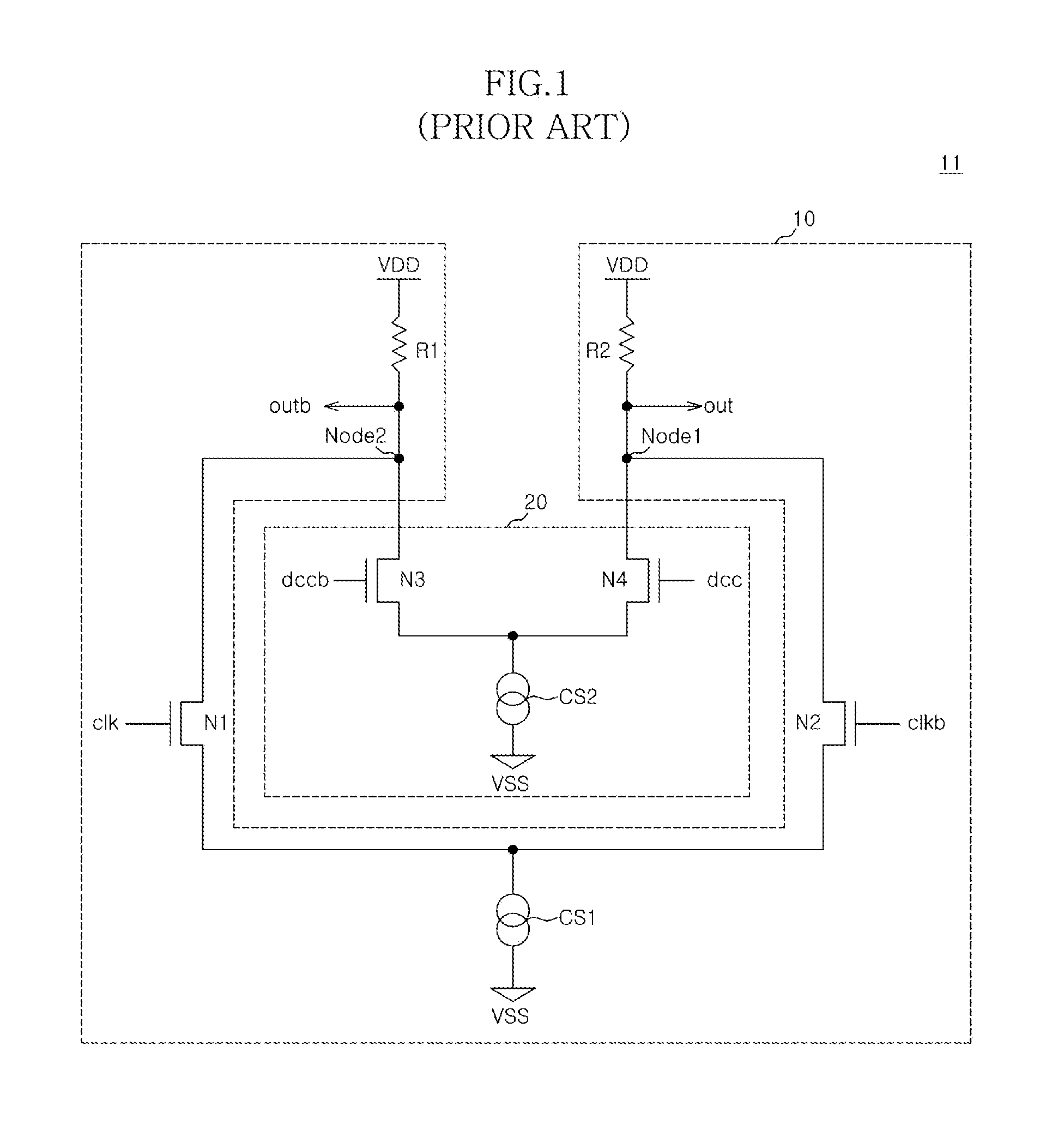
However, because the duty cycle correction circuit of FIG. 1 uses two differential amplifiers, each having a current source, the current consumption can be prohibitively high for certain applications and is generally increased due to the dual differential amplifiers.

Method used


Image

  • Duty cycle correction circuit and method for correcting duty cycle
  • Duty cycle correction circuit and method for correcting duty cycle
  • Duty cycle correction circuit and method for correcting duty cycle

Examples


Embodiment Construction

.”

BRIEF DESCRIPTION OF THE DRAWINGS

[0015]The above and other aspects, features and other advantages of the subject matter of the present disclosure will be more clearly understood from the following detailed description taken in conjunction with the accompanying drawings, in which:

[0016]FIG. 1 is a circuit diagram illustrating a conventional duty cycle correction circuit;

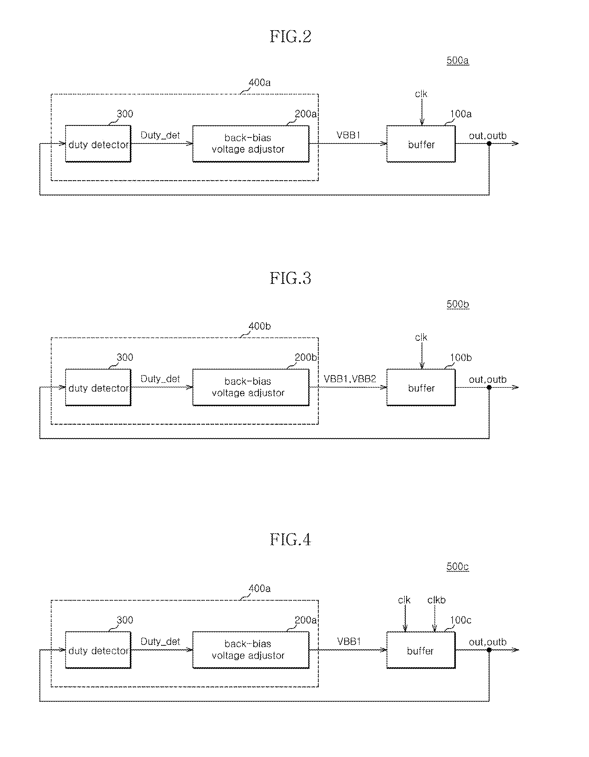
[0017]FIGS. 2 to 5 are block diagrams illustrating a duty cycle correction circuit according to various example embodiments;

[0018]FIG. 6 is a block diagram illustrating an example of a back-bias voltage adjustor included in the circuit shown in FIGS. 2 and 4;

[0019]FIG. 7 is a block diagram illustrating an example of a back-bias voltage adjustor included in the circuit shown in FIGS. 3 and 5

[0020]FIGS. 8 to 11 are circuit diagrams illustrating an example of a buffer and the back-bias voltage adjustors included in the circuit shown in FIGS. 2 to 5; and

[0021]FIG. 12 is a wave form of a clock signal and an output signal...


PUM


Abstract

A duty cycle correction circuit capable of reducing current consumption and that includes a back-bias voltage supply circuit for supplying back-bias voltages, wherein a duty cycle of an input clock is reflected on the back-bias voltages; and a buffer for adjusting the duty cycle of the input clock and configured to receive the back-bias voltages.

Description

CROSS-REFERENCES TO RELATED APPLICATION[0001]This application claims the benefit under 35 U.S.C. 119(a) of Korean Patent application No. 10-2008-0013454, filed on Feb. 14 2008, in the Korean Patent Office, the disclosure of which is incorporated herein by reference in its entirety as if set forth in full.BACKGROUND[0002]1. Technical Field[0003]The embodiments described herein relate to a semiconductor integrated circuit and, more particularly, to a duty cycle correction circuit and method for correcting duty cycle of a digital clock in a semiconductor integrated circuit.[0004]2. Related Art[0005]It is often important to exactly control the duty cycle of a digital clock signal used by a semiconductor integrated circuit. A digital clock signal with a duty cycle of 50% is commonly used in conventional digital clock circuits within conventional semiconductor integrated circuits. A duty cycle of 50% means that the clock signal is low for the same amount of time that it is high or active....

Claims


Application Information

Patent Timeline
IPC IPC(8): H03K3/017
CPCG11C8/04H03K2217/0018H03K5/1565G11C7/22G11C5/14
Inventor SONG, HEE WOONGKIM, YONG JUHAN, SUNG WOOJANG, JAE MINKIM, HYUNG SOOLEE, JI WANGPARK, CHANG KUNOH, IC SUCHOI, HAE RANGHWANG, TAE JIN
Owner SK HYNIX INC
Learn More