Energy Saving Control for a Field Device

Active Publication Date: 2010-11-25
VEGA GRIESHABER GMBH & CO
View PDF34 Cites 30 Cited by
  • Summary
  • Abstract
  • Description
  • Claims
  • Application Information

AI Technical Summary

Benefits of technology

[0007]Consequently, the control unit can be optimised in relation to its capability in the operating mode, and the monitoring unit can be optimised to use as little energy as possible when waiting for the activation signal. In this way the energy consumption of the control maybe reduced. The control unit may be used for controlling electrical and / or electronic components, for example a measuring unit and / or a communication unit of the field device. In this arrangement the measuring unit is used to control a sensor that is connected to the field device, in other words to determine measured values. The communication unit is designed to transmit the measured values determined by the measuring unit to a receiver. Transmission may be by way of a line or by radio. The receiver may be a further field device or a central facility of a process monitoring- and / or process control system whose component the field device is.
[0037]Such a field device may be able to operate with very low current consumption, if necessary batter-operated or accumulator-operated. In this arrangement a powerful CPU can be controlled by a power saving unit or monitoring unit in order to be switched on by said unit when an event occurs. The monitoring unit can also switch off communication interfaces (GSM, Ethernet or similar) and switch a measuring unit or the sensor off in order to achieve a very low standby current of the field device.

Problems solved by technology

In operating mode, in which the control unit is active and may carry out calculations and / or may communicate with other components of the field device, the control unit consumes a relatively large amount of energy when compared to its sleep mode.
However, in the case of a control for a field device, the time phases in which the control unit is in operating mode may be relatively short when compared to the phases in which it is in sleep mode.

Method used


Image

  • Energy Saving Control for a Field Device
  • Energy Saving Control for a Field Device
  • Energy Saving Control for a Field Device

Examples


Embodiment Construction

[0051]The illustrations in the figures are diagrammatic and not to scale. In the following description of the figures the same reference characters are used for identical or similar elements.

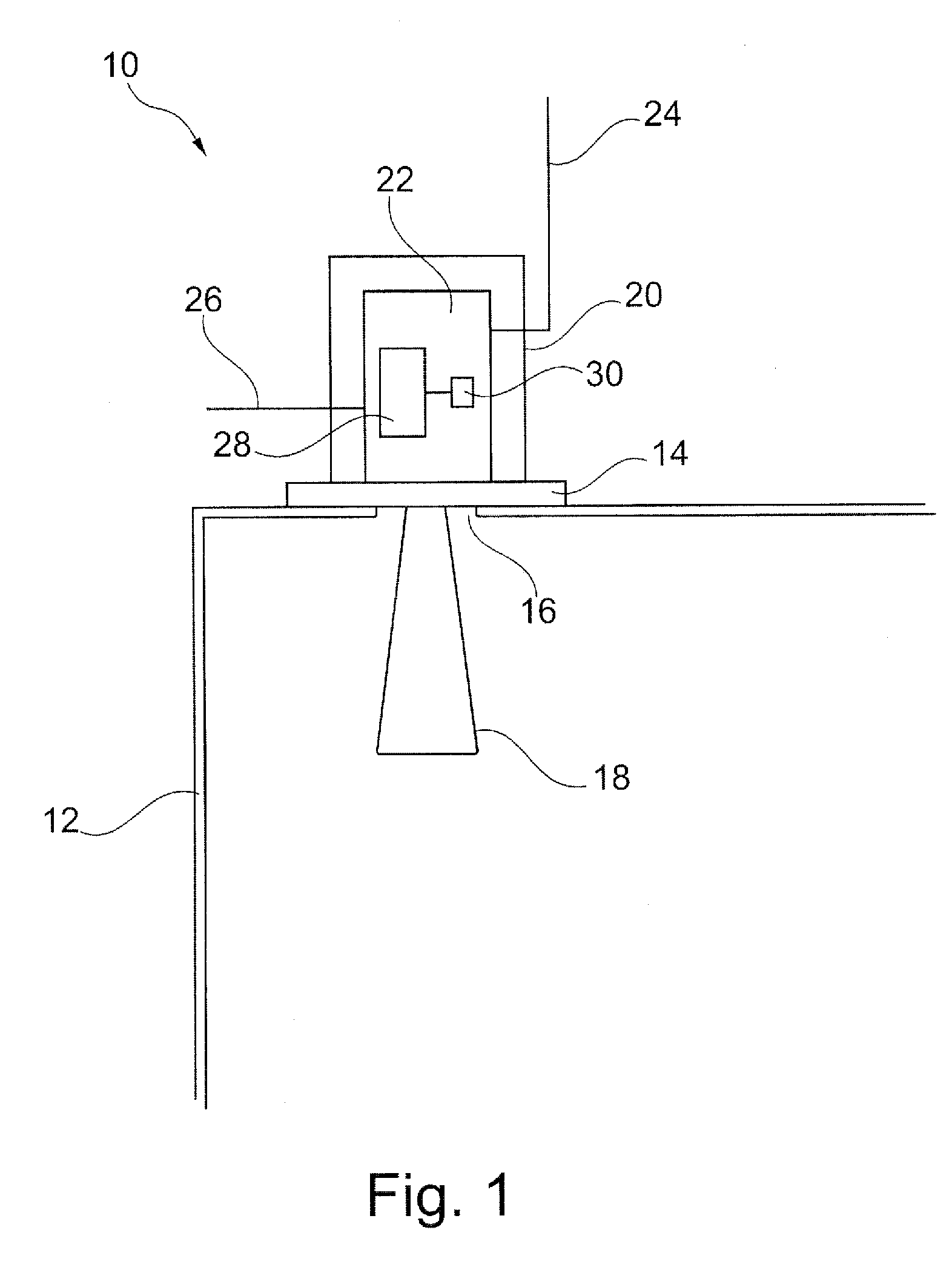
[0052]FIG. 1 shows a field device 10 that is attached to a container 12 and that is, for example, designed as a fill level radar. The field device 10 is, for example, attached at an opening 16 of the container by means of a mounting plate 14, with a sensor 18 projecting through said opening 16 into the interior of the container 12. Opposite the sensor 18, with reference to the mounting plate 14, there is a housing 20 in the interior of which a control 22 for the field device 10 is arranged. The control 22 in the outer region of the container 12 can be connected to an antenna 24 in order to exchange data with a receiver by way of a radio connection. Furthermore, the control 22 can be connected by a line 26 for data communication and / or for the supply of energy.

[0053]The control 22 comprises a con...


PUM


Abstract

A control for a field device comprises a monitoring unit that is separate from a control unit for controlling the field device which monitoring unit, when the control unit is in a sleep mode, waits for an activation signal in order to switch the control unit to the operating mode.

Description

FIELD OF THE INVENTION[0001]The invention relates to measuring systems-in technical facilities, for example for measuring a fill level, a limit, a pressure or a flow. In particular, the invention relates to a control device for a field device; to a field device comprising a control; to a method for controlling a field device; to a program element for a control; and to a computer-readable medium.TECHNOLOGICAL BACKGROUND[0002]Field devices as components of a process monitoring system are operated in technical facilities, for example for measuring the fill level, the limit or the pressure in a container, or for measuring the flow through a pipe. To this effect many of the field devices comprise sensors by means of which the actual measuring processes are carried out. The process monitoring system can comprise further field devices, which are, for example, used for forwarding and processing the acquired measured values to a central facility. Each of the field devices comprises a control...

Claims


Application Information

Patent Timeline
IPC IPC(8): G06F1/32
CPCG06F1/3203
Inventor ALLGAIER, VOLKERISENMANN, ANDREAS
Owner VEGA GRIESHABER GMBH & CO
Why Eureka
Try Eureka