
Method for Placing and Mechanically Connecting Panels

a technology of mechanical connection and connecting panel, which is applied in the direction of walls, building material handling, construction, etc., can solve the problems of laborious and difficult to carry out, especially the manipulation of the new-laying panel, which is extremely complicated and requires great strength, and achieves the effect of convenient carrying ou

Active Publication Date: 2009-08-06
INTERGLARION LTD (AT)
View PDF8 Cites 94 Cited by
  • Summary
  • Abstract
  • Description
  • Claims
  • Application Information

AI Technical Summary

Benefits of technology

[0011]The aspect of the invention is therefore to disclose a method for laying and mechanically connecting panels of the type mentioned at the outset, wherein the method can be carried out more easily and in particular by one floorer.
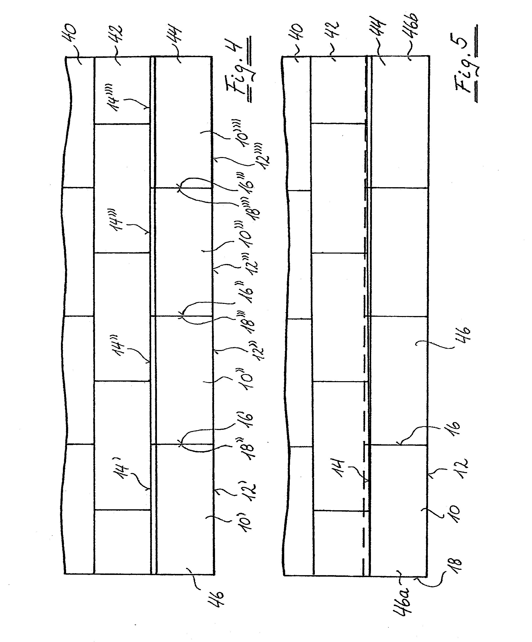
[0012]This aspect is attained according to the invention by a method of the type mentioned at the outset. Initially, in a first step, a plurality of panels of a panel row that is to be newly laid, and preferably all of the panels of the panel row that is to be newly laid, are connected to one another in pairs by way of locking elements of their respective second pairs of locking elements. In a second step, the panels connected to one another of the panel row that is to be newly laid are connected to the panels of the panel row that has already been laid by pivoting locking elements of their respective first pairs of locking elements into one another. This may be performed by working in sections, in one or more sub-steps, beginning at one of the ends of the panel row that is to be newly laid and utilizing a torsional flexibility of the panels about an axis running parallel to the first pair of side edges, along to the other of its ends. In this method two properties of the panels are utilized, which had not hitherto been considered for use in the course of laying the panels: the strength of the engagement of the locking elements; and the torsional flexibility of the panels about an axis running parallel to its first pair of side edges.

Problems solved by technology

This known method has the disadvantage of being very laborious and difficult to carry out.
The former case is laborious, because one person cannot lay the panels alone.
In the second case, however, a single floorer is faced with the problem that particularly manipulating the panel that is to be newly laid is extremely complicated and requires great strength.

Method used


Image

  • Method for Placing and Mechanically Connecting Panels
  • Method for Placing and Mechanically Connecting Panels
  • Method for Placing and Mechanically Connecting Panels

Examples


Embodiment Construction

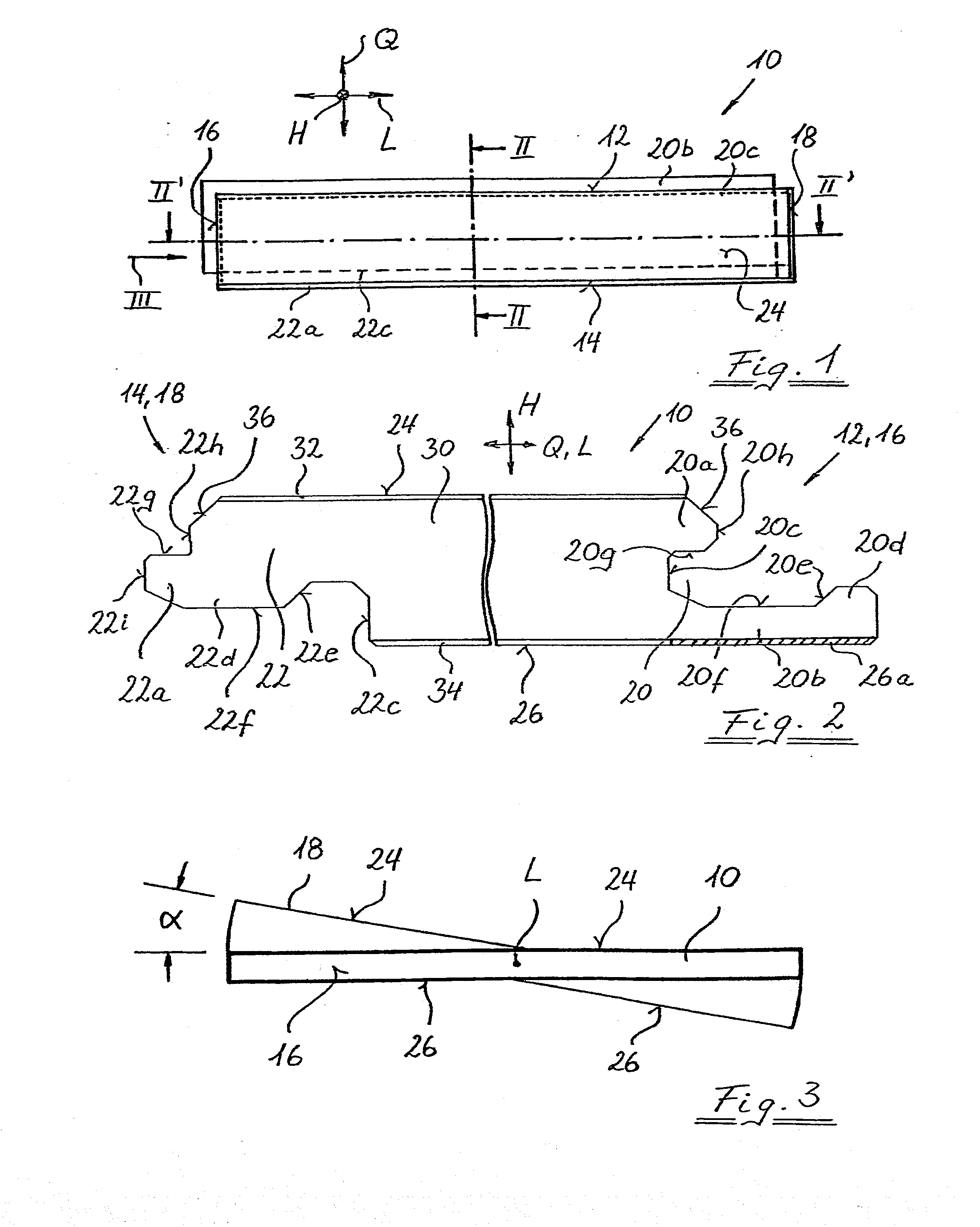
[0032]In FIG. 1 a panel that can be laid with the aid of the method according to the invention is designated in general by panel 10. The panel 10 is embodied in a rectangular manner and comprises two side edges 12 and 14, running parallel to one another, of the long sides of the panel 10 running in the longitudinal direction L, and two side edges 16 and 18, running parallel to one another, of the short sides of the panel 10 running in the transverse direction Q. Both pairs of side edges 12 / 14 and 16 / 18 are provided with locking elements that are embodied essentially in the form of a groove 20 and a tongue 22 (see FIG. 2).

[0033]The groove 20 is limited by an upper lip 20a near to the visible surface 24 of the panel 10 and by a lower lip 20b near to the base area 26 of the panel 10 facing away from the visible surface 24, i.e., distant from the visible surface 24. In the exemplary embodiment shown the lower lip 20b is embodied longer than the upper lip 20a and projects beyond the side...


PUM


Abstract

The invention relates to a method for laying and mechanically connecting panels in rows parallel to one another. The method includes forming a super panel comprising a first plurality of panels in a first panel row, to be newly laid, the super panel being formed by connecting together second pairs of locking elements in adjacent panels of the first panel row. The method also includes connecting the super panel to a second plurality of panels in an already laid second panel row by working in sections, beginning at an end of the super panel, by utilizing a torsional flexibility of the super panel to engage the first pair of locking elements. During the connecting, the first plurality of panels do not move relative to each other along the second pair of edges.

Description

CROSS-REFERENCE TO RELATED APPLICATIONS[0001]The present application is a U.S. National Stage of International Patent Application No. PCT / EP2006 / 004998 filed May 24, 2006, and claims priority of German Patent Application No. 10 2005 024 366.5 filed May 27, 2005. Moreover, the disclosure of International Patent Application No. PCT / EP2006 / 004998 is expressly incorporated by reference herein in its entirety.BACKGROUND OF THE INVENTION[0002]1. Field of the Invention[0003]The invention relates to a method for laying and mechanically connecting panels in rows parallel to one another, the panels having respectively a first pair of side edges lying opposite one another and a second pair of side edges lying opposite one another, a first pair of locking elements being assigned to the first pair of side edges as well as a second pair of locking elements being assigned to the second pair of side edges, the pairs of locking elements being embodied essentially in the form of a tongue and a groove...

Claims


Application Information

Patent Timeline
IPC IPC(8): E04B1/00E04C2/40
CPCE04F15/02E04F2201/0153E04F15/02033
Inventor SCHITTER, LEONHARD
Owner INTERGLARION LTD (AT)
Learn More