
Projector emitting laser light of multiple colors and optical axis adjusting method for the projector

a projector and laser light technology, applied in the field of projectors and optical axis adjustment methods of projectors, can solve the problems of shrinkage on curing, the techniques disclosed in the foregoing three publications cannot overcome,

Inactive Publication Date: 2009-07-30
FUNAI ELECTRIC CO LTD
View PDF8 Cites 7 Cited by
  • Summary
  • Abstract
  • Description
  • Claims
  • Application Information

AI Technical Summary

Benefits of technology

[0020]An object of the invention is to provide a projector that can keep a state in which optical axes of light fluxes of laser light of multiple colors match together, as well as an optical axis adjusting method of the light fluxes of the laser light of the multiple colors.
[0023]According to the projector and the optical axis adjusting method for the projector can keep a state in which the optical axes of the light fluxes of the laser light of the multiple colors match together.

Problems solved by technology

However, the techniques disclosed in the foregoing three publications cannot overcome the following problem.
Since the light source and the lens holder are fixed together by the adhesive in a three-point contact fashion, shrinkage on curing may occur in the adhesives due to a temperature or the like, and this may displace the optical axes of the laser light fluxes of multiple colors that were adjusted to match together.

Method used


Image

  • Projector emitting laser light of multiple colors and optical axis adjusting method for the projector
  • Projector emitting laser light of multiple colors and optical axis adjusting method for the projector
  • Projector emitting laser light of multiple colors and optical axis adjusting method for the projector

Examples


Embodiment Construction

[0032]An embodiment of the invention will be described below with reference to the drawings.

[0033](Structure)

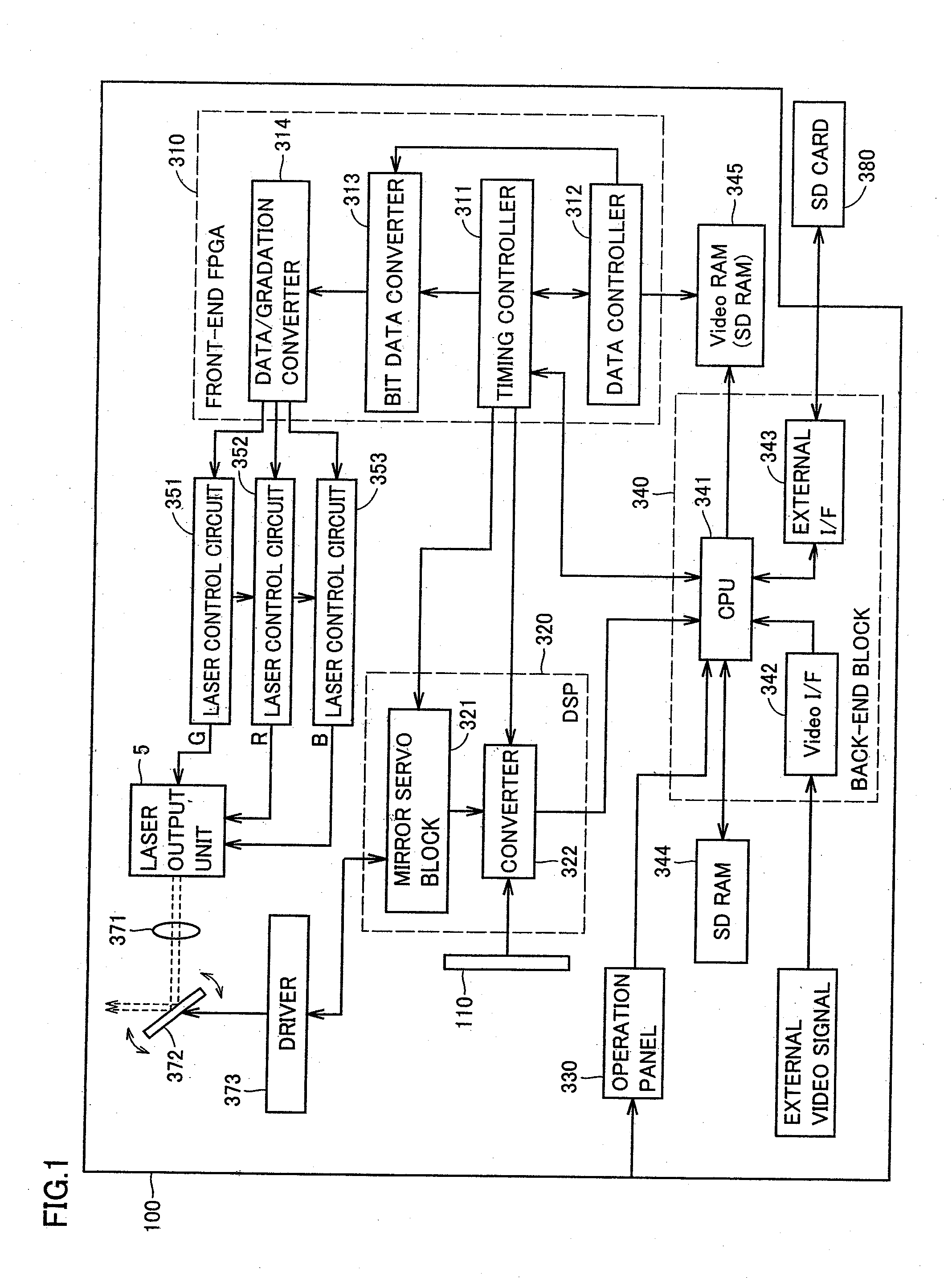
[0034]FIG. 1 shows a structure of a projector of the embodiment of the invention.

[0035]Referring to FIG. 1, a projector 100 includes a front-end FPGA (Field Programmable Gate Array) 310, a digital signal processor 320, an operation panel 330, a back-end block 340, an SDRAM (Synchronous Dynamic Random Access Memory) 344, a video RAM (Random Access Memory) 345, laser control circuits 351, 352 and 353, a laser output unit 5, a galvanometer mirror 372 and a driver 373. Driver 373 includes, for example, a driver motor, a coil or the like.

[0036]Front-end FPGA 310 includes a data / gradation converter 314, a timing controller 311, a data controller 312, and a bit data converter 313. Digital signal processor 320 includes a mirror servo block 321 and a converter 322.

[0037]Operation panel 330 is arranged on a front surface or side surface of a casing of projector 100. Operation panel 330...


PUM

PropertyMeasurementUnit
Angleaaaaaaaaaa
Coloraaaaaaaaaa

Abstract

A first light output unit integrally has a first light source and a first prism, a second light output unit integrally has a second light source and a second prism, and a third light output unit integrally has a third light source and a third prism. A first surface of the first prism and a second surface of the second prism are adhered together by an adhesive with a first film located therebetween, and first film passes green laser light and reflects blue laser light. A third surface of the second prism and a fourth surface of the third prism are adhered together by an adhesive with a second film located therebetween, and second film passes the green laser light and the blue laser light, and reflects red laser light.

Description

BACKGROUND OF THE INVENTION[0001]1. Field of the Invention[0002]The invention relates to a projector and an optical axis adjusting method for the projector, and particularly to a projector emitting laser light of multiple colors and an optical axis adjusting method for the projector.[0003]2. Description of the Background Art[0004]Various techniques have been proposed for reducing sizes of a projector.[0005]For example, Japanese Patent Gazette No. 2006-527392 has disclosed a projector integrally having a light source chip and an optically transparent beam-forming element that substantially surrounds a hemispherical area around the light source chip.[0006]Japanese Patent Laying-Open No. 2005-208183 has disclosed a projector that leads light fluxes emitted from LED (Light Emitting Diode) light sources of three (i.e., RGB) colors to a light pipe after combining these light fluxes by color combining means, leads the light from the light pipe to an image display element arranged substanti...

Claims


Application Information

Patent Timeline
IPC IPC(8): G03B21/28B29C65/14B29C65/52
CPCG02B27/104G02B27/1073G02B27/145G03B21/2033H04N9/3129H04N9/3152G03B21/14G03B21/2066G03B21/208G03B33/12
Inventor TAKAHASHI, YUTAKAMATSUBARA, HIROKINISHIGAKI, HIROSHIMURAYAMA, MANABU
Owner FUNAI ELECTRIC CO LTD
Learn More