Automatic insitu post process cleaning for processing systems having turbo pumps

a technology of processing system and turbo pump, which is applied in the direction of electrostatic cleaning, crystal growth process, chemical vapor deposition coating, etc., can solve the problems of inability to run production, significant source of particles, and significant end of line yield loss

Inactive Publication Date: 2009-07-30
TEXAS INSTR INC
View PDF2 Cites 4 Cited by
  • Summary
  • Abstract
  • Description
  • Claims
  • Application Information

AI Technical Summary

Problems solved by technology

Buildup of deposited layers and particulates within turbo pumps of such tools is generally the leading cause of particles added at certain process steps, such as high density plasma shallow trench isolation (HDP STI).
Particles added at HDP STI deposition are known to lead to “ripout” type defects (e.g. voids) and other defects which can result in significant end of line yield loss.
Soon after their introduction, turbomolecular pumps were found to be a significant source of particles due to the buildup of deposition within them over time.
While the system is offline, it is not available to run production.
This method is time consuming with a total time to complete being about 2.5 to 3 hours, and also being manual in many aspects, is thus susceptible to mistakes.
The amount of maintenance required to maintain acceptable particle performance for processing systems, such as deposition systems, is high due to lengthy maintenance cycles associated with the heavily manual turbo clean steps and results in substantial cost as well as an increase in cycle time.

Method used


Image

  • Automatic insitu post process cleaning for processing systems having turbo pumps
  • Automatic insitu post process cleaning for processing systems having turbo pumps

Examples


examples

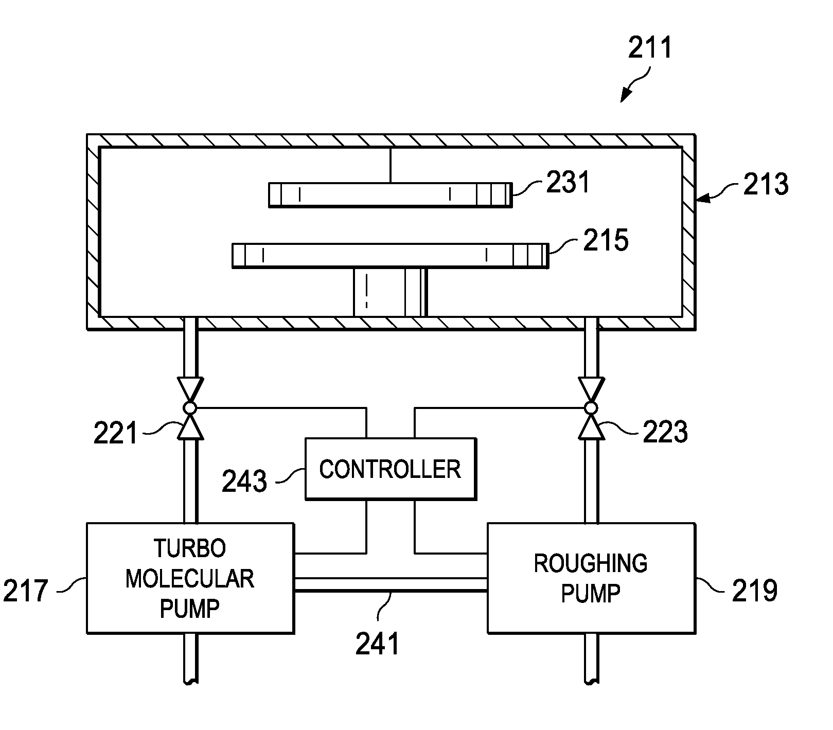
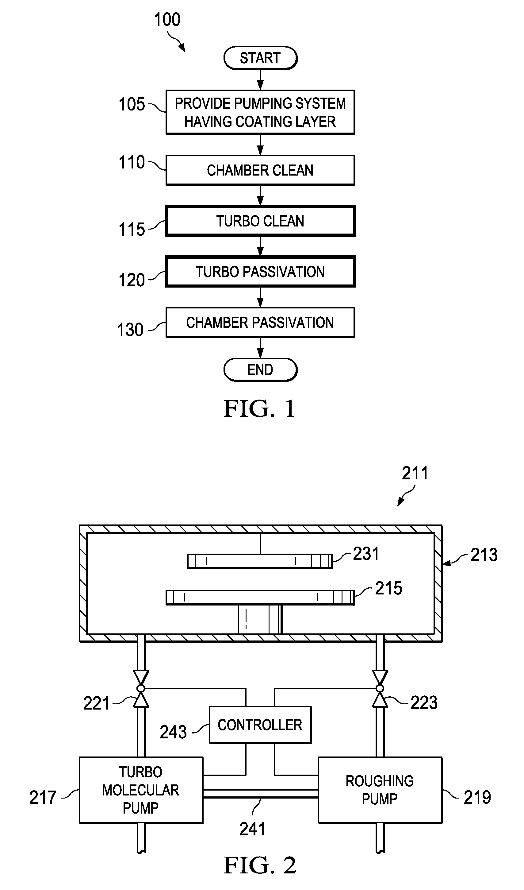
[0022]Parameters for an exemplary process system clean sequence including automatic turbo clean 100 described above relative to FIG. 1, is provided below in the case of a HDP oxide deposition system, according to a particular embodiment of the invention. Step 110, RF chamber clean, can be broken up into two sub-steps. The first sub-step can comprise a high flow RF chamber clean (NF3 flow=800 to 990 sccm, O2 flow=100 sccm, pressure=1 to 2 Torr, high frequency (e.g. 13.56 MHz) RF power=4,000 to 4,300 Watts). The second sub-step can comprise a low flow chamber clean (NF3 flow=100 to 300 sccm, O2 flow 0 to 30 sccm, pressure=1 to 2 Torr, high frequency (e.g. 13.56 MHz) RF power=4,000 to 4,500 Watts). Step 115, the automatic turbo clean, can comprise (NF3 flow=990 sccm, O2 flow=100 sccm, pressure=˜100 mTorr (not actively controlled), and high frequency (e.g. 13.56 MHz) RF power=4000 Watts. Automatic Turbo passivation, step 120 can comprise H2 flow=1000 sccm, O2 flow=300 sccm, Ar flow=300 ...


PUM

PropertyMeasurementUnit
pressureaaaaaaaaaa
total timeaaaaaaaaaa
pressureaaaaaaaaaa

Abstract

An automatic method (100) of in-situ cleaning a processing system (211) including a process chamber (213) pumped by a roughing pump (219) and a turbomolecular pump (217) includes the steps of automatically performing a first RF plasma clean (110) (referred to herein as a chamber clean) to clean the process chamber, wherein the turbomolecular pump (217) is isolated and the roughing pump (219) pumps the processing chamber (213). The turbomolecular pump (217) is automatically switched on to pump the processing chamber (213). While the turbomolecular pump is pumping the processing chamber (213), a second RF plasma clean (115) (referred to herein as an automatic turbo clean) is performed clean the turbomolecular pump (217). In embodiments of the invention the turbo clean (115) automatically sets at least one gas flow, an RF power, and a pressure in the chamber (213).

Description

FIELD OF THE INVENTION[0001]Embodiments of the invention relate to cleaning semiconductor processing systems having turbomolecular pumped process chambers.BACKGROUND[0002]Achieving high yields in semiconductor processes requires that the processes have low defect densities. Particulates are one important class of defects. Particulates can introduced by processes including etch, film deposition (e.g. sputter, LPCVD or PECVD), and chemical mechanical planarization (CMP). The defects are generally characterized and defect source analysis (DSA) is performed to identify the source of the defects. Process changes can then be implemented in order to reduce or eliminate the various defect types, and the results can be verified through further inspections.[0003]Processes which include an evacuated process chamber include some pumping means. In the cases of a deposition system, the inner surfaces of the pump as well as the process chamber generally gets coated with the deposition. As known in...

Claims


Application Information

Patent Timeline
Patent Type & Authority Applications(United States)
IPC IPC(8): B08B6/00
CPCB08B7/0035C23C16/4405H01J37/32862H01J37/3244H01J37/32834C30B25/14
Inventor NEW, JASON J.IBARRA-RIVERA, ANTONIOBOCKEMEHL, JR., JOE M.
Owner TEXAS INSTR INC
Why Eureka
Try Eureka