
Ultra-low temperature freezer, refrigeration system and vacuum apparatus

a vacuum apparatus and freezer technology, applied in the field of ultra-low temperature freezers, refrigeration systems and vacuum devices, can solve the problems of reducing the flow rate of liquid refrigerant obtained by gas refrigerant liquefaction of the supercooler, and affecting the cooling efficiency of the main cooler. , to achieve the effect of shortening the cool-down time, simple structure and enhancing the cooling efficiency of the main cooler

Inactive Publication Date: 2009-07-30
SHIN MEIWA IND CO LTD
View PDF5 Cites 17 Cited by
  • Summary
  • Abstract
  • Description
  • Claims
  • Application Information

AI Technical Summary

Benefits of technology

[0076]As described so far, the first or second aspect of the invention is directed to a refrigeration system comprising a main cooler for cooling a cooling target and a supercooler for cooling refrigerant in its primary side with refrigerant in its secondary side, wherein the refrigeration system further comprises a supercooler refrigerant flow rate increasing device for allowing liquid refrigerant to flow into the secondary side of the supercooler at a higher rate than into the main cooler. Therefore, sufficient cooling of gas refrigerant in the primary side of the supercooler can be ensured to enhance the cooling efficiency of the main cooler. This provides stable cooling of the cooling target and shortens the cool-down time taken to cool the cooling target down to an ultra-low temperature level.
[0077]In the third aspect of the invention, the refrigeration system further comprises: a main refrigerant circuit provided with the main cooler and the main cooler pressure reducing element; and a sub refrigerant circuit that is connected to the main refrigerant circuit to branch off therefrom and provided with the supercooler pressure reducing element, and the supercooler refrigerant flow rate increasing device is configured so that the minimum cross sectional area of the sub refrigerant circuit is larger than the maximum cross sectional area of the main refrigerant circuit. Thus, when the refrigerant discharged from the primary side of the supercooler is distributed into the main and sub refrigerant circuits, gas-liquid mixture refrigerant can flow into the sub refrigerant circuit at a higher rate than into the main refrigerant circuit, and, in turn, liquid refrigerant can flow into the sub refrigerant circuit at a higher rate than into the main refrigerant circuit. In this manner, the supercooler refrigerant flow rate increasing device can be achieved.
[0078]In the fourth aspect of the invention, the refrigeration system further comprises: a main refrigerant circuit provided with the main cooler and the main cooler pressure reducing element; and a sub refrigerant circuit that is connected to the main refrigerant circuit to branch off therefrom and provided with the supercooler pressure reducing element, and the supercooler refrigerant flow rate increasing device is configured so that the maximum height of the sub refrigerant circuit at the bifurcation of the main and sub refrigerant circuits is lower than the minimum height of the main refrigerant circuit at the bifurcation. Thus, when the refrigerant discharged from the primary side of the supercooler is distributed into the main and sub refrigerant circuits, liquid refrigerant of the gas-liquid mixture refrigerant can flow into the sub refrigerant circuit of relatively small height, and, in turn, liquid refrigerant can flow into the sub refrigerant circuit at a higher rate than into the main refrigerant circuit. Therefore, the supercooler refrigerant flow rate increasing device can be achieved with a simple structure.
[0079]According to the fifth aspect of the invention, since in the refrigeration system of the third aspect the maximum height of the sub refrigerant circuit at the bifurcation of the main and sub refrigerant circuits is lower than the minimum height of the main refrigerant circuit at the bifurcation, the behaviors and effects of the third and fourth aspects can synergistically act to further enhance the cooling efficiency of the main cooler.
[0080]According to the sixth aspect of the invention, since moisture in a vacuum chamber of a vacuum apparatus is frozen by cooling it using the main cooler of the refrigeration system, this provides a stable vacuum condition in the vacuum chamber and shortened cool-down time, and shortened exhaust time and in turn enhanced production efficiency.
[0081]In the seventh aspect of the invention, an oil separator for removing refrigerator oil from the refrigerant mixture is disposed in the defrosting circuit of the ultra-low temperature freezer. Thus, it can be prevented that, during defrosting, the refrigerator oil in the refrigerant mixture is supplied from the defrosting circuit to the cooler to solidify in the cooler, and an increase in pressure loss that would be caused when a plurality of oil separators were disposed in series between the compressor and the condenser can be prevented. This provides enhanced cooling efficiency while ensuring good circulation of the refrigerant mixture.

Problems solved by technology

The above conventional refrigeration systems, however, have problems described below.
However, the refrigerant passing through the bifurcation of the main and sub refrigerant circuits into the main cooler and the secondary side of the supercooler is not fully composed of liquid refrigerant but is supplied to both the coolers as gas-liquid mixture refrigerant partly containing gas refrigerant.
Therefore, even if the system is configured so that refrigerant flowing through the main cooler is equal in flow rate to refrigerant flowing through the supercooler, if the flow rate of liquid refrigerant into the secondary side of the supercooler is low, this provides a shortage of cooling of gas refrigerant in the primary side thereof.
The flow rate of liquid refrigerant obtained by gas refrigerant liquefaction of the supercooler is correspondingly reduced, which invites deteriorated cooling efficiency of the main cooler.
As a result, in the case of load variations of the cooling target to be cooled by the main cooler, there arises a problem of impossibility to stably cool the cooling target against such load variations or a problem of extended cool-down time taken for the main cooler to cool down the cooling target from normal to ultra-low temperature level.
(2) Further, when the normal operation of the freezer is halted and a defrosting operation is performed to supply the discharge gas from the compressor to the cooler through the defrosting circuit and thereby defrost the cooler, if refrigerator oil has failed to be completely removed by the oil separator and remains in it at the start of the defrosting operation, it may flow through the defrosting circuit and may be supplied to the cooler still at an ultra-low temperature level, which causes a problem that the refrigerator oil solidifies in the cooler.

Method used


Image

  • Ultra-low temperature freezer, refrigeration system and vacuum apparatus
  • Ultra-low temperature freezer, refrigeration system and vacuum apparatus
  • Ultra-low temperature freezer, refrigeration system and vacuum apparatus

Examples


embodiment 1

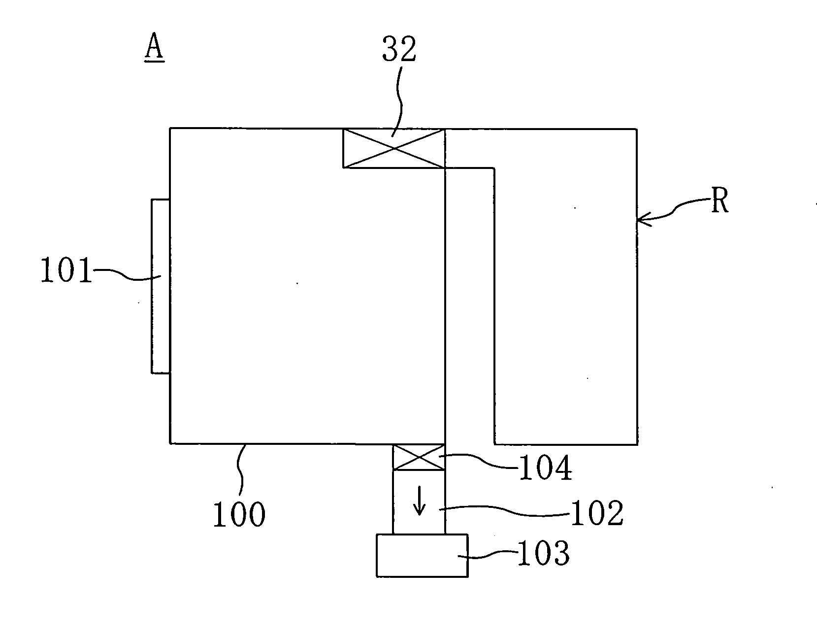
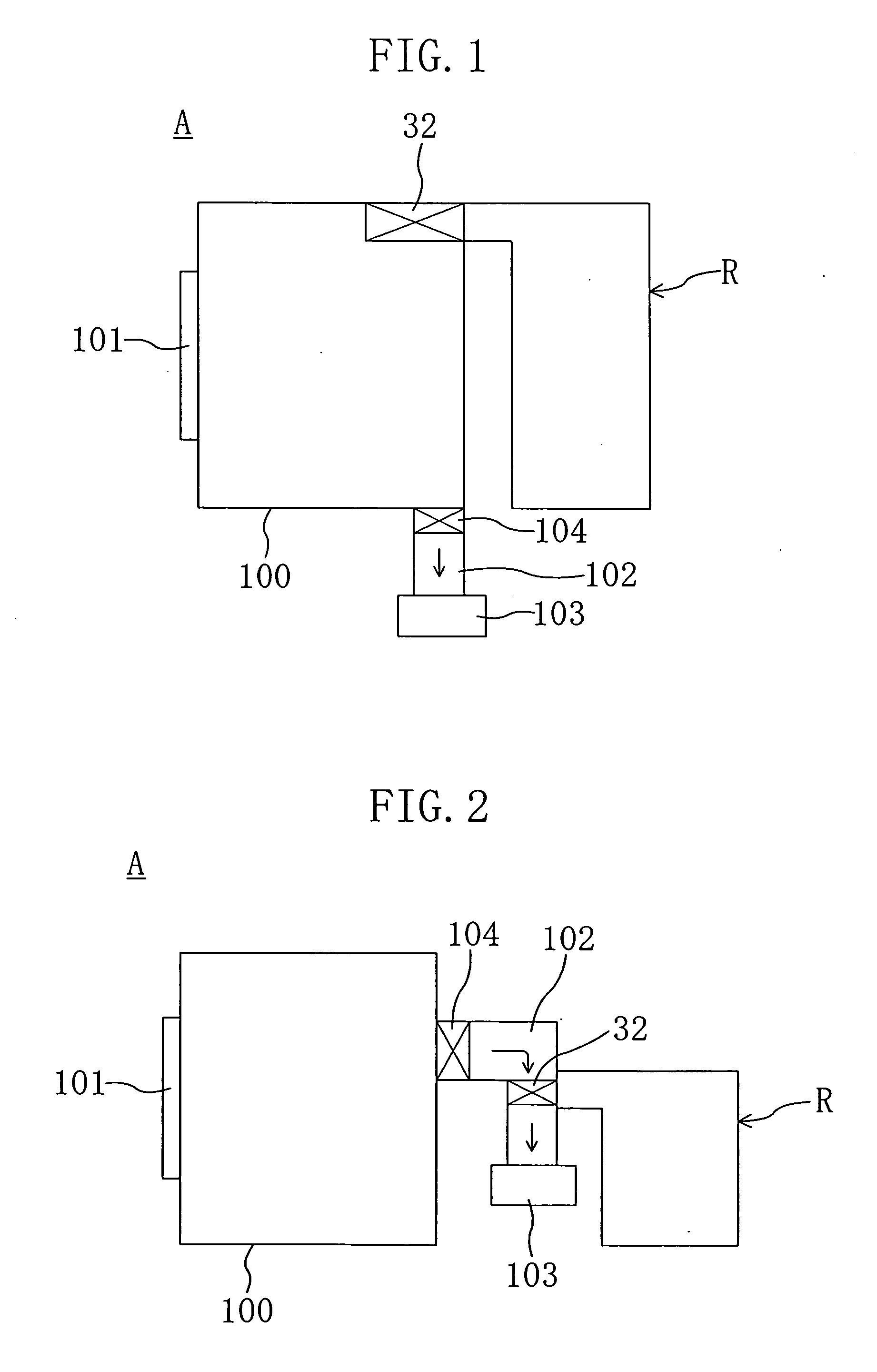
[0178]FIG. 1 shows an example of the layout of a vacuum deposition apparatus A serving as a vacuum apparatus according to an embodiment of the invention. Reference numeral 100 denotes a vacuum chamber in which films are deposited on unshown substrates (also referred to as wafers) with the inside kept under vacuum. The vacuum chamber 100 has a carry-in-and-out opening (not shown) that can be opened and closed by an opening and closing door 101. Substrates on which films are to be deposited are carried in the vacuum chamber 100 or the substrates on which films have been deposited are carried out of it, in each case with the opening and closing door 101 open. The vacuum chamber 100 is connected through a communicating passage 102 with a vacuum pump 103. A gate valve 104 is disposed at the connecting point of the communicating passage 102 and the vacuum chamber 100 to switch between providing flow communication between them and interrupting the flow communication of them by turning the ...

embodiment 2

[0205]FIG. 6 shows Embodiment 2 of the invention (where the same parts as in FIGS. 1 to 5 in this and following embodiments are identified by the same reference characters and a detailed description thereof is not given). In Embodiment 1, the flow rate of liquid refrigerant into the secondary side 31b of the supercooler 31 is kept higher than that into the cryocoil 32 by setting the height of the sub refrigerant circuit 39 to be lower than that of the main refrigerant circuit 38. In contrast, in this embodiment, the sub refrigerant circuit 39 and the main refrigerant circuit 38 are located at the same height but the sub refrigerant circuit 39 has a larger cross sectional area than the main refrigerant circuit 38.

[0206]More specifically, in this embodiment, in contrast to Embodiment 1, the collecting portion 35a and main branch portion 35b of the branch pipe 35, the main refrigerant pipe 2a connected to these portions, the sub-branch portion 35c of the branch pipe 35, and the sub ref...

embodiment 4

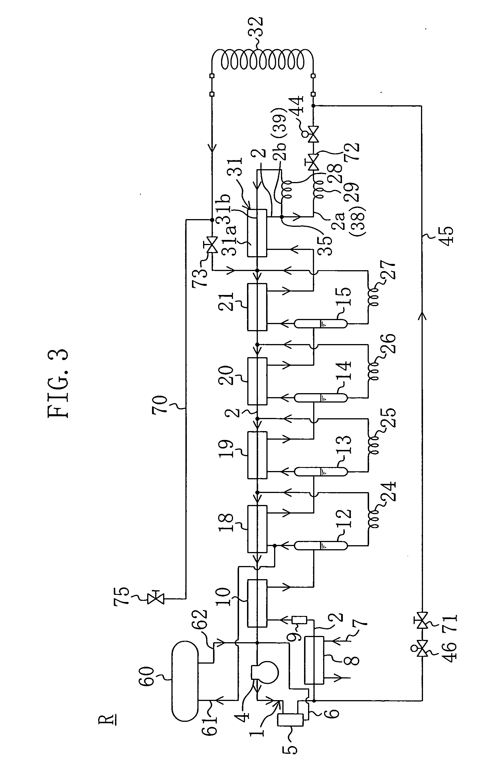
[0217]FIG. 9 shows the overall configuration of an ultra-low temperature freezer R according to Embodiment 4 of the invention. In the following Embodiments 4 to 13, the structure of the branch pipe 35 described in Embodiments 1 to 3 is not essential.

[0218]Embodiment 4 is characterized by the configuration of the defrosting circuit 45. Specifically, as shown in FIG. 9, a second oil separator 50 for separating refrigerator oil, such as lubrication oil for a compressor, from gas refrigerant is disposed between the upstream end of the defrosting circuit 45 and the solenoid shut-off valve 46 (and the oil separator 5 connected to the discharge part of the compressor 4 is referred to as a first oil separator). The refrigerator oil separated by the second oil separator 50 is returned, as with the first oil separator 5, through the oil return pipe 6 to the suction side of the compressor 4. The second oil separator 50 is disposed at a location along the defrosting circuit 45 at which the dist...


PUM


Abstract

In an ultra-low temperature freezer (R) using refrigerant mixture in which plural kinds of refrigerants having different boiling points are mixed, in order to ensure the flow rate of liquid refrigerant into a supercooler (31) and enhance the cooling efficiency of a cryocoil (32), the ultra-low temperature freezer (R) comprises: a main refrigerant circuit (38) provided with the cryocoil (32) and a capillary tube (29); and a sub refrigerant circuit (39) that is connected at the upstream end to the upstream end of the main refrigerant circuit (38) to branch off therefrom and provided with a capillary tube (28), and the ultra-low temperature freezer (R) is configured so that the sub refrigerant circuit (39) is lower in height than the main refrigerant circuit (38). Thus, gas-liquid mixture refrigerant discharged from the primary side (31a) of the supercooler (31) flows into the sub refrigerant circuit (39) at a higher rate than into the main refrigerant circuit (38) and, in turn, liquid refrigerant flows more into the sub refrigerant circuit (39) than into the main refrigerant circuit (38).

Description

TECHNICAL FIELD[0001]This invention relates to an ultra-low temperature freezer for creating a cold environment at an ultra-low temperature level, a refrigeration system for the same purpose and a vacuum apparatus provided with one of them.BACKGROUND ART[0002]Conventionally known refrigeration systems for creating a cold environment at an ultra-low temperature level of −100° C. or below include mixed refrigerant type ultra-low temperature freezers in which a refrigerant circuit is charged with a non-azeotropic refrigerant mixture obtained by mixing plural kinds of refrigerants having different boiling temperatures, as disclosed, for example, in Patent Documents 1, 2 and 3. An ultra-low temperature freezer of such kind is placed in, for example, a vacuum chamber of a vacuum deposition apparatus for use in manufacturing substrates (wafers), and used to raise the vacuum level in the vacuum chamber by trapping moisture or the like in it by freezing.[0003]The refrigerant circuit of the a...

Claims


Application Information

Patent Timeline
Patent Type & Authority Applications(United States)
IPC IPC(8): F25D21/00F25B1/00F25B43/02F25B7/00F25B9/00
CPCF25B9/006F25B39/028F25B45/00F25B49/005F25D2400/30F25B2500/26F25B2700/1931F25D11/04F25B2500/01F25B41/42
Inventor TAKAHASHI, MASAYUKIYAGI, MASAFUMISHIMIZU, HIROMASATOMOZAWA, AKIRAIKEDA, MASAHIKOSHIONO, MASAHITO
Owner SHIN MEIWA IND CO LTD
Learn More