
Outboard motor

a technology for outboard motors and oil supply devices, which is applied in the direction of propulsive elements, marine propulsion, vessel construction, etc., can solve the problems of inability to dispose of the intermediate speed reduction device on the intermediate portion of the drive shaft, and the above-mentioned intermediate speed reduction device cannot be disposed immediately below the engine, so as to achieve a simple and compact arrangement

Active Publication Date: 2009-07-16
YAMAHA MOTOR CO LTD
View PDF6 Cites 6 Cited by
  • Summary
  • Abstract
  • Description
  • Claims
  • Application Information

AI Technical Summary

Benefits of technology

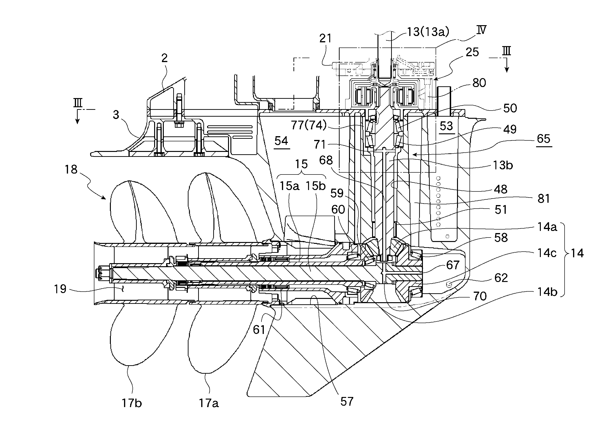
[0008]In view of the problems described above, preferred embodiments of the present invention provide an oil supply device for an outboard motor in which an intermediate speed reduction device is mounted on a drive shaft and can be lubricated sufficiently in a simple and compact arrangement.
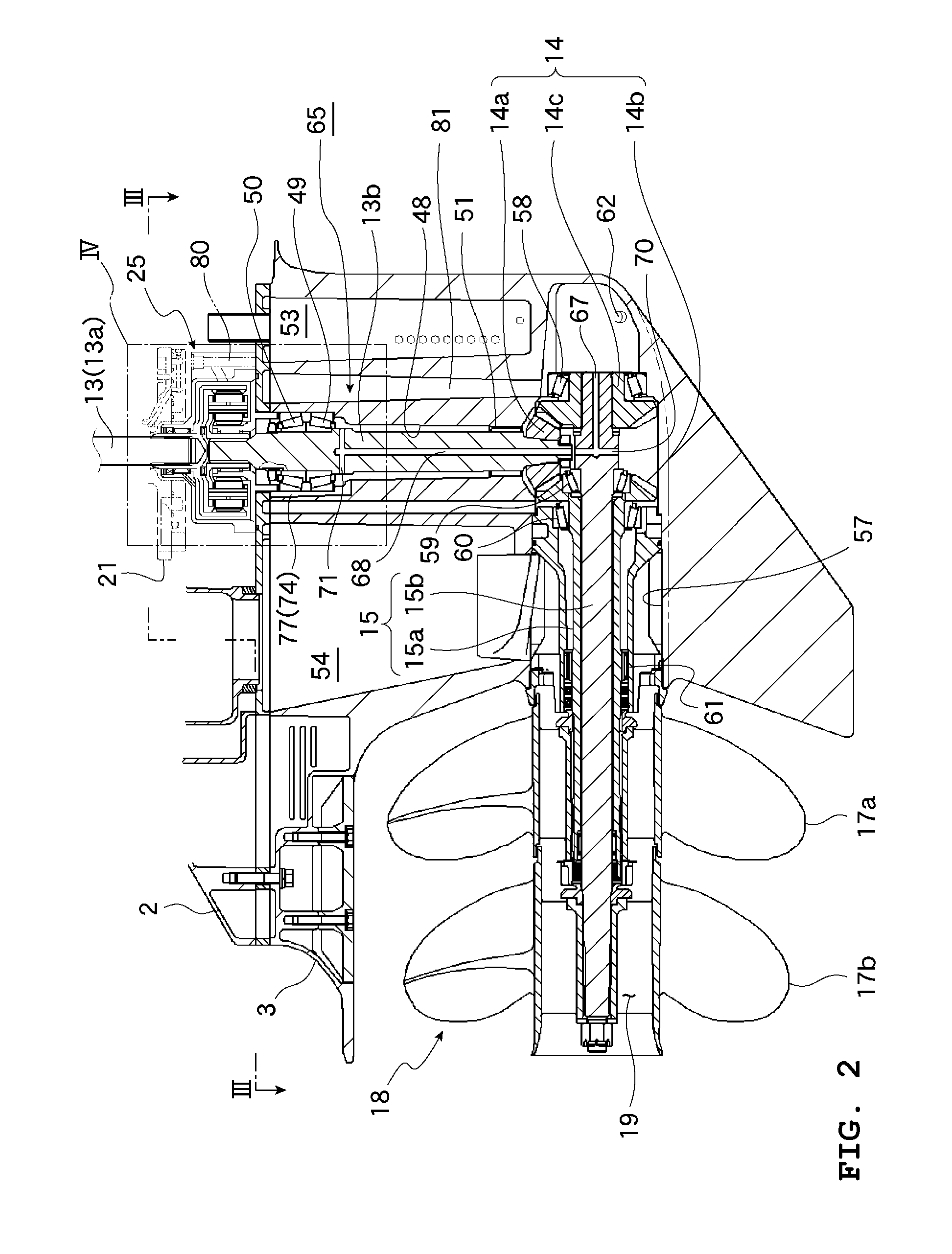
[0020]The intermediate speed reduction device can be supplied with oil for lubrication around the propeller shaft through only existing components, thereby achieving a significantly simple and compact arrangement.
[0021]The oil supplied to the center of the intermediate speed reduction device is preferably spread to the outer periphery of the intermediate speed reduction device by centrifugal force, thereby sufficiently lubricating the intermediate speed reduction device in a simple arrangement.
[0022]The oil supplied to the intermediate speed reduction device is reliably circulated to the bottom of the casing via the oil return passage. Therefore, the intermediate speed reduction device can be lubricated sufficiently.
[0023]Air inside the intermediate speed reduction device can be reliably released from the oil return passage by removing the drain plug while replenishing the oil.

Problems solved by technology

Depending on the internal layout of the outboard motor, however, the intermediate speed reduction device discussed above cannot be disposed immediately below the engine, in which case it is conceivable to dispose the intermediate speed reduction device on an intermediate portion of the drive shaft.
Since lubrication using engine oil is difficult in such an arrangement, it has been impossible to dispose the intermediate speed reduction device on an intermediate portion of the drive shaft.

Method used


Image

  • Outboard motor
  • Outboard motor
  • Outboard motor

Examples


Embodiment Construction

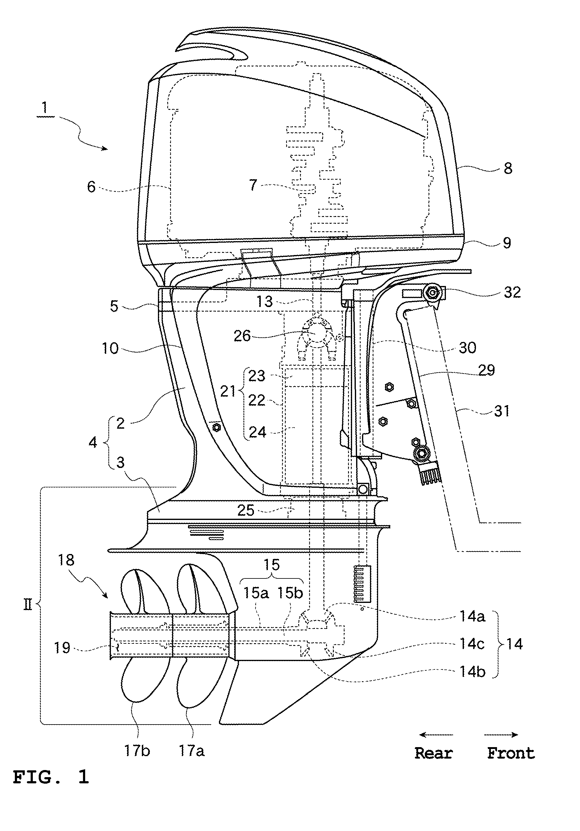
[0030]Preferred embodiments of the present invention will be described hereinafter with reference to FIGS. 1 to 4.

[0031]FIG. 1 is a right side view of an outboard motor in accordance with a preferred embodiment of the present invention, with the right side of the drawing indicating the forward direction of the boat. An outboard motor 1 includes a casing 4 including an upper case 2 and a lower case 3 provided therebelow, and an engine 6 installed above the casing 4 via a generally flat mounting plate 5. The engine 6 is preferably a water-cooled engine with six cylinders in a V configuration, for example, and is placed on the mounting plate 5 with a crankshaft 7 extending vertically. The engine 6 is covered by an upper cover 8 and a lower cover 9 which are removable. The right and left sides of the upper case 2 are covered by a side cover 10 which is also removable.

[0032]A drive shaft 13 is journaled vertically inside the casing 4. The drive shaft 13 is divided into a plurality of sec...


PUM


Abstract

An oil supply device includes an axial oil passage and an intersecting oil passage provided in a propeller shaft, an axial oil passage and an intersecting oil passage provided in a drive shaft, and an oil guide passage. The intersecting oil passages allow oil inside the axial oil passages to be spouted radially of the shaft by centrifugal force generated as the shafts rotate. The oil is then supplied via the oil guide passage to an intermediate speed reduction device. As a result, it is possible to sufficiently lubricate an intermediate speed reduction device mounted on a drive shaft through a simple and compact arrangement.

Description

BACKGROUND OF THE INVENTION[0001]1. Field of the Invention[0002]The present invention relates to an oil supply device for an outboard motor that lubricates an intermediate speed reduction device provided on an intermediate portion of a drive shaft.[0003]2. Description of the Related Art[0004]WO 2007 / 007707 discloses an outboard motor having an engine installed in a vertical arrangement above a casing, with a drive gear provided at the lower end of a crankshaft of the engine and a driven gear provided at the upper end of a drive shaft extending downward inside the casing. In the outboard motor, the drive gear and the driven gear are meshed with each other in order to transmit the rotation of the crankshaft to the drive shaft.[0005]Increasing the number of teeth of the drive gear relative to the driven gear allows the gears to serve as an intermediate speed reduction device, which reduces the rotation of the crankshaft before being transmitted to the drive shaft.[0006]The gear transmi...

Claims


Application Information

Patent Timeline
Patent Type & Authority Applications(United States)
IPC IPC(8): B63H20/00
CPCB63H20/002
Inventor FUKUOKA, YOSHIHITONAKAMURA, DAISUKEYAMAUCHI, HIROTOSHIHASEGAWA, SACHIYO
Owner YAMAHA MOTOR CO LTD
Learn More