
Mixing and pumping system for use with installed hydronic radiant floor heating systems and the like

a technology of hydronic radiant floor and pumping system, which is applied in the direction of sustainable buildings, space heating and ventilation details, domestic heating details, etc., can solve the problem that none of the existing systems lends itself readily to connection to different kinds of fluid heaters (electric)

Inactive Publication Date: 2009-07-16
MIRCHILDON MICHAEL
View PDF24 Cites 15 Cited by
  • Summary
  • Abstract
  • Description
  • Claims
  • Application Information

AI Technical Summary

Benefits of technology

[0009]The invention in its broadest expression is an improved module for connection to an installed hydronic radiant floor heating system having a fluid supply line and a fluid return line, the improvement comprising the combination of:

Problems solved by technology

Systems which have been used to date for supplying fluid to an installed hydronic radiant floor heating system and the like are not readily adaptable to different heating loads and are energy-inefficient when used for simultaneously controlling heating of a number of rooms, a task hereinafter referred to as “multiple zoning”.
Further, none of the existing systems lends itself readily to connection to different kinds of fluid heaters (electric, gas, solar).

Method used


Image

  • Mixing and pumping system for use with installed hydronic radiant floor heating systems and the like
  • Mixing and pumping system for use with installed hydronic radiant floor heating systems and the like

Examples


Embodiment Construction

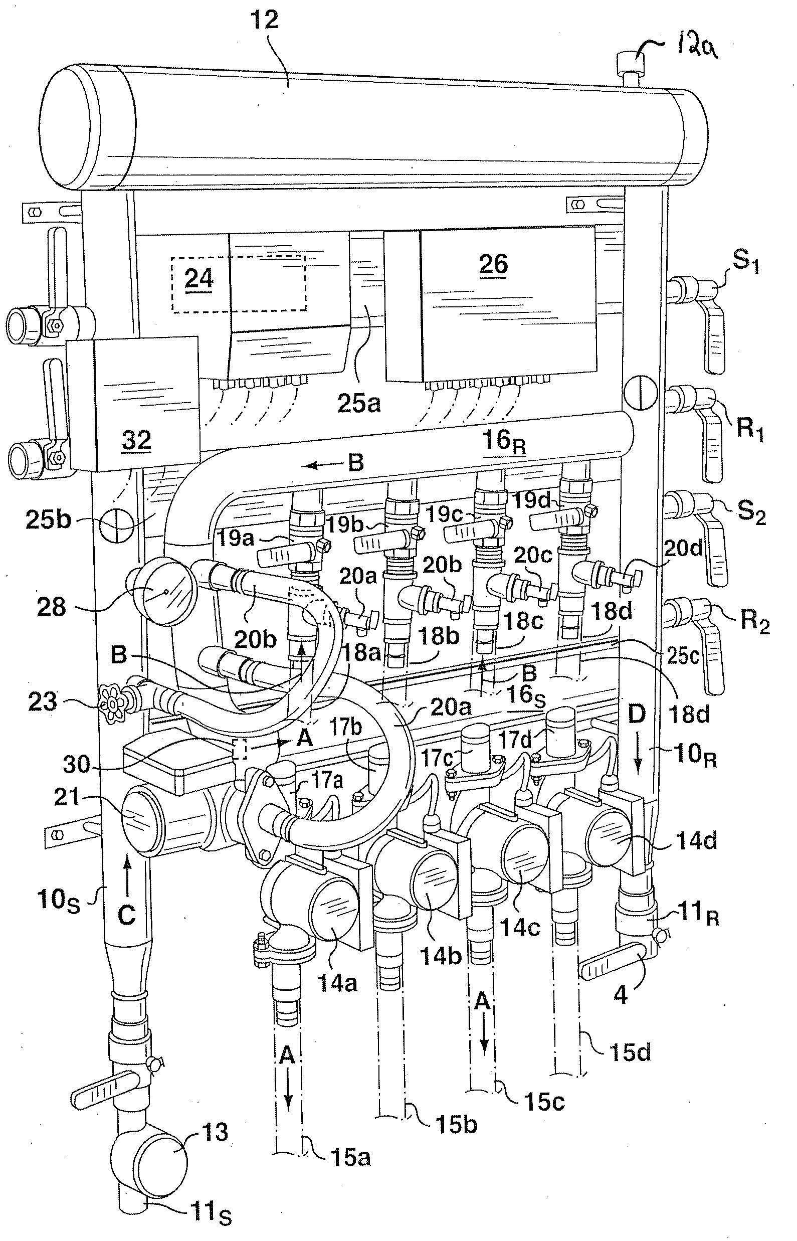
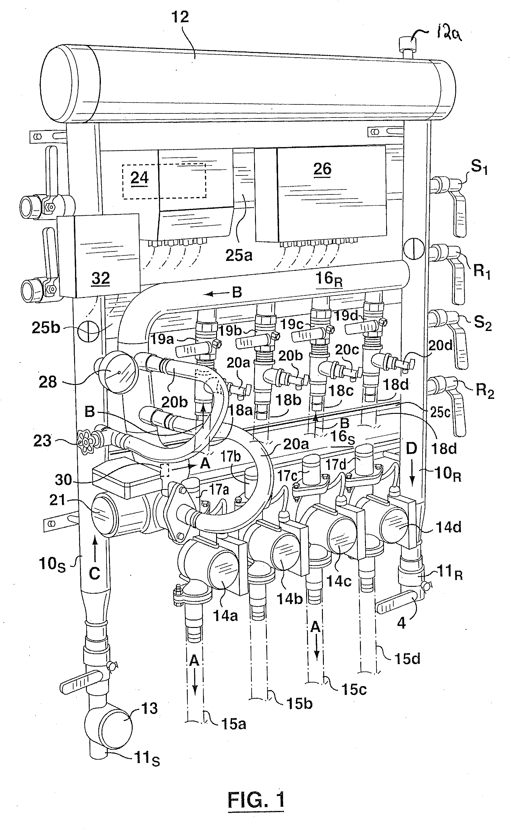
[0014]Apparatus according to the invention comprises a primary (boiler) comprising parallel supply and return channels 10S and 10R, respectively which communicate and are connected to a larger diameter conduit 12, which also functions as an air elimination tank, air being expelled through air vent 12a.

[0015]Hot water from the boiler or other heat source is introduced into main supply channel 10S through intake valve 11S by means of a boiler pump (not shown). The intake flow rate is measured by flowmeter 13. Water is recycled directly to the boiler through return valve 11R on return channel 10R.

[0016]Manifold pumps 14a, 14b, 14c and 14d impel water into one or more manifolds through respective feeding channels 15a-15d from a secondary (manifold) loop. The secondary manifold loop is a generally horizontal U-shaped tube having a lower horizontal channel 16s feeding water into manifold pumps 14a-14b through respective isolation valves 17a-17d and then out into feeding channels 15a-15d ...


PUM


Abstract

A mixing and pumping module for use with an installed hydronic radiant floor heating system is described. The module comprises a primary loop for circulating water to and from a boiler; a secondary loop in valve fluid communication with said primary loop and with the manifold of a hydronic radiant floor heating system, for circulating water into and out of the manifold; and means for regulating the flows of water through the primary loop, secondary loop and manifold loop, for selective delivery of heating capacities over a wide range of heating requirements, in a configuration which is compact and readily mounted to a frame for installation on a wall of the residence or commercial building in which the system is installed.

Description

RELATED APPLICATION[0001]This application claims priority to, and any other benefit of, U.S. Provisional Patent Application No. 61 / 021,124 filed Jan. 15, 2008, which is herein incorporated by reference.BACKGROUND OF THE INVENTION[0002]1. Field of the Invention[0003]This invention relates to a hydronic radiant floor system for pumping heated water from a boiler or other heat source through one or more manifolds (tubing laid in a pattern underneath a floor, in the case of the floor heating system). The system of the invention is characterized by simpler access and maintenance and more efficient heat delivery when compared with radiant floor heating systems currently installed in residential and commercial buildings.[0004]2. Description of the Related Art[0005]In general terms, a radiant heating system supplies heat directly to the floor or wall or ceiling panels in a house. “Hydronic” radiant floor heat refers to those systems in which hot water is circulated through tubing laid out i...

Claims


Application Information

Patent Timeline
Patent Type & Authority Applications(United States)
IPC IPC(8): F16K17/38F24D5/10
CPCF24D3/105F24D3/1058F24D3/1066F24D3/12Y02B30/745F24D2220/042F24D2220/044F24D2220/046F24H9/122F24D19/1012Y10T137/1987Y02B30/70Y02B30/00F24H9/13
Inventor MIRCHILDON, MICHAEL
Owner MIRCHILDON MICHAEL
Learn More