Worm reducer and electric power steering apparatus

a technology of electric power steering and worm reducer, which is applied in the direction of toothed gearings, gearings, vehicle components, etc., can solve the problems of reducing the life of the device, affecting the operation of the device, so as to improve the flexibility of the device layout, prevent the effect of device life reduction, and reduce the reducing mechanism

Active Publication Date: 2010-02-16
NSK LTD
View PDF10 Cites 10 Cited by
  • Summary
  • Abstract
  • Description
  • Claims
  • Application Information

AI Technical Summary

Benefits of technology

[0012]This invention has been accomplished under the above circumstance. An object of the invention is to provide a worm reducer which can improve its downsizing and life by enhancing strength in an increased module while keeping the lead angle of a reversely operable worm and a center distance between the worm and worm wheel, and an electric power steering apparatus provided with such a worm reducer.
[0029]wherein a rotation of the electric motor is reduced and transmitted to the steering shaft through the worm and the worm wheel to thereby assist steering operation.
[0030]In the worm according to the invention, since the worm wheel teeth are formed so that the lead angle of the worm wheel is smaller than that of the worm, the quantity of lead (pitch) of the worm wheel for each rotation of the worm can be reduced. For this reason, under the condition that the center distance between the worm and worm wheel and the reduction ratio of the worm reducer are fixed, the module of the worm wheel teeth can be increased as compared with the conventional worm reducer. As a result, the high strength of the worm and worm wheel can be realized. On the other hand, under the condition that the reduction ratio of the worm reducer and the module of the worm wheel teeth are fixed, the center distance between the worm and worm wheel can be decreased as compared with the conventional worm reducer. For this reason, the worm reducer can be downsized.
[0031]Further, in the worm reducer according to the invention, the worm wheel teeth are formed on the peripheral surface of the worm wheel using a machining electro-deposition worm in which abrasive grains are electro-deposited on the screw faces of another worm having the same shape as the worm to be combined with the worm wheel. Thus, since the lead angles at the area other than the pitch points of the worm wheel teeth can be also matched, interference can be avoided and further the tooth faces with a large contact area between the worm wheel teeth and the screw faces can be formed. As a result, the interference can be avoided without increasing the face pressure so that the endurance and abrasion-resistance of the worm reducer can be improved thereby preventing reduction in the life of the worm reducer.
[0032]Additionally, the machining electro-deposition worm may be employed in which abrasive grains are electro-deposited on screw faces of another worm having the same shape of tooth faces as that in the worm to be combined with the worm wheel and having a larger diameter of the tooth tip circle and a larger diameter of the tooth base circle than those of the worm. For this reason, the same advantage as that obtained when the machining electro-deposition worm having the same shape as that of the worm to be combined with the worm wheel can be obtained. In addition, tooth tip gaps when the worm to be actually meshed is combined with the worm wheel can be obtained. As a result, the dimension error and secular abrasion can be dealt with and the transmission efficiency can be improved.
[0034]Thus, life reduction of the device can be prevented. In addition, since the reducing mechanism is downsized, flexibility of the layout of the device can be improved.

Problems solved by technology

Therefore, the mounting layout of the electric motor was limited.
However, in the conventional orthogonal type worm reducer, it was difficult to assure sufficient strength of the worm wheel teeth 121.
However, in these worm 110 and worm wheel 120, there was fear of generating interference at the area other than the pitch points.
In this case, however, the contacts at the mutual meshing area are point contacts and so the face pressure in the meshing area becomes high.

Method used


Image

  • Worm reducer and electric power steering apparatus
  • Worm reducer and electric power steering apparatus
  • Worm reducer and electric power steering apparatus

Examples


embodiments

[0049]Now referring to the drawings, an explanation will be given of embodiments of the invention.

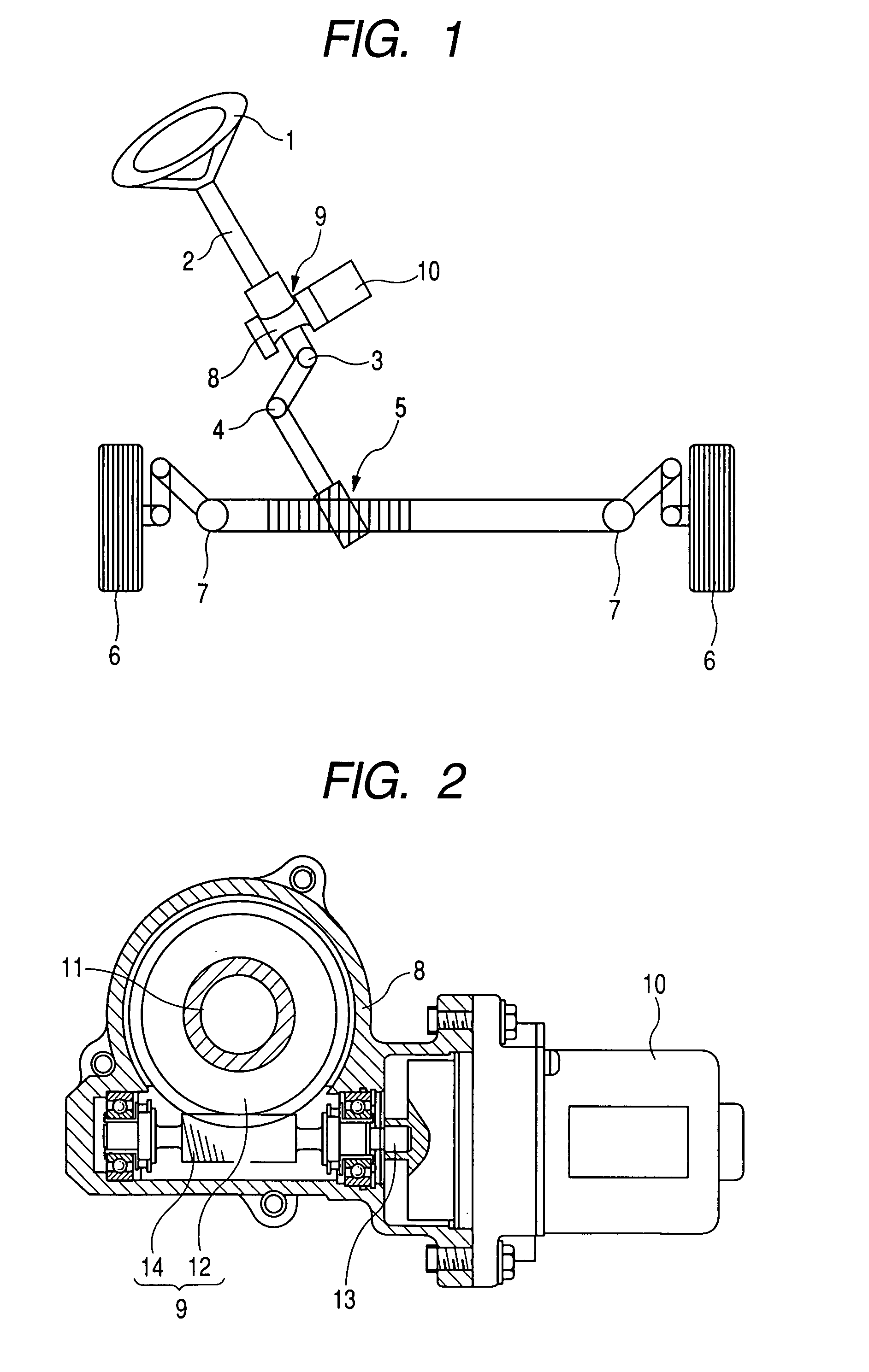
[0050]FIG. 1 is a view for explaining the schematic configuration of a column type electric power steering apparatus according to this embodiment. In FIG. 1, a column shaft 2 of a steering handle 1 is connected to tie rods 7, 7 of steering wheels 6, 6 via universal joints 3, 4 and a pinion-rack mechanism 5. The column shaft 2 is provided with a reducing mechanism (or worm reducer) 9 incorporated within a housing 8. An electric motor 10 for steering assistance connected to the column shaft 2 through the reducing mechanism 9 is attached to the housing 8.

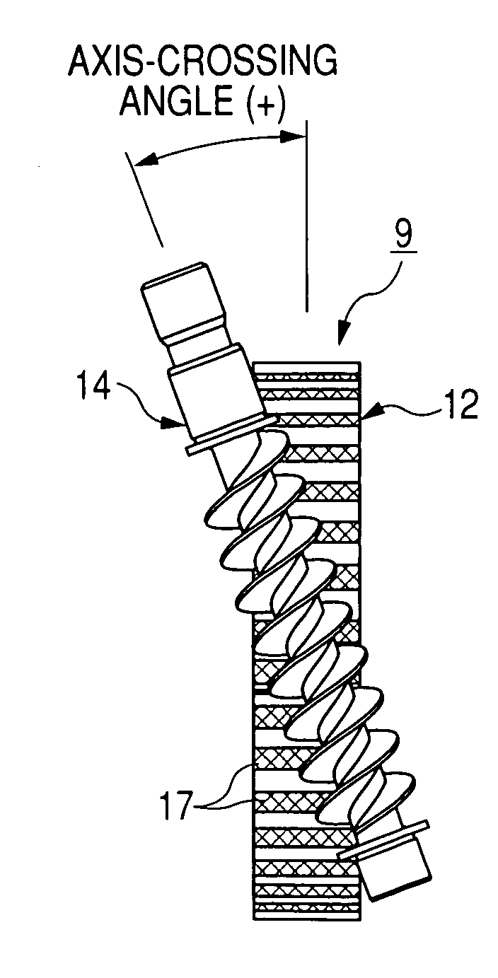
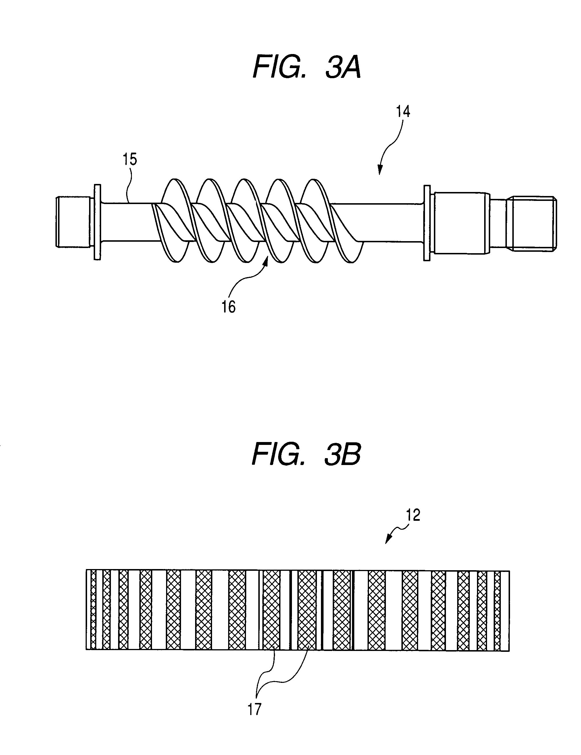
[0051]FIG. 2 is a sectional view of the main part of the reducing mechanism 9 in a power steering device according to this embodiment. In FIG. 2, the housing 8 incorporates a worm wheel 12 press-fitted into the outer periphery of a steering shaft 11 extending from the column shaft 2 and a worm 14 coaxially to a rotary shaft 13 of the elect...


PUM


Abstract

In a worm reducer for reducing the rotation transmitted to a worm and transmitting the reduced rotation to a worm wheel, the worm reducer being composed of the worm with screw faces formed on its outer periphery and the worm wheel with worm wheel teeth formed on its peripheral surface, the worm wheel teeth being in mesh with the screw faces of the worm, the worm wheel teeth are formed so that the lead angle of the worm wheel is smaller than that of the worm.

Description

BACKGROUND OF THE INVENTION[0001]1. Field of the Invention[0002]This invention relates to a worm reducer for reducing the rotation transmitted to a worm and transmitting the reduced rotation to a worm wheel, and an electric power steering apparatus provided with the worm reducer.[0003]2. Description of Related Art[0004]In recent years, a vehicle is provided with an electric power steering apparatus for assisting steering by reducing the rotation of an electric motor prepared as a driving source for steering assistance through a reducing mechanism and transmitting the reduced rotation to a steering mechanism. Such an electric power steering apparatus adopts a worm reducer consisting of a worm and a worm wheel as a reducing mechanism for transmitting steering assistant force to a steering shaft by the electric motor.[0005]FIG. 9 is a view showing a conventional worm reducer. FIG. 9(a) is a view showing a worm and FIG. 9(b) is a view showing the peripheral surface of a worm wheel. In F...

Claims


Application Information

Patent Timeline
IPC IPC(8): F16H1/16
CPCB62D5/0409F16H1/16Y10T74/19828
Inventor MAEDA, ATSUSHI
Owner NSK LTD
Why Eureka
Try Eureka