
Method and apparatus for duty cycle pre-distortion and two-dimensional modulation

Active Publication Date: 2009-07-02
AVAGO TECH INT SALES PTE LTD
View PDF5 Cites 7 Cited by
  • Summary
  • Abstract
  • Description
  • Claims
  • Application Information

AI Technical Summary

Benefits of technology

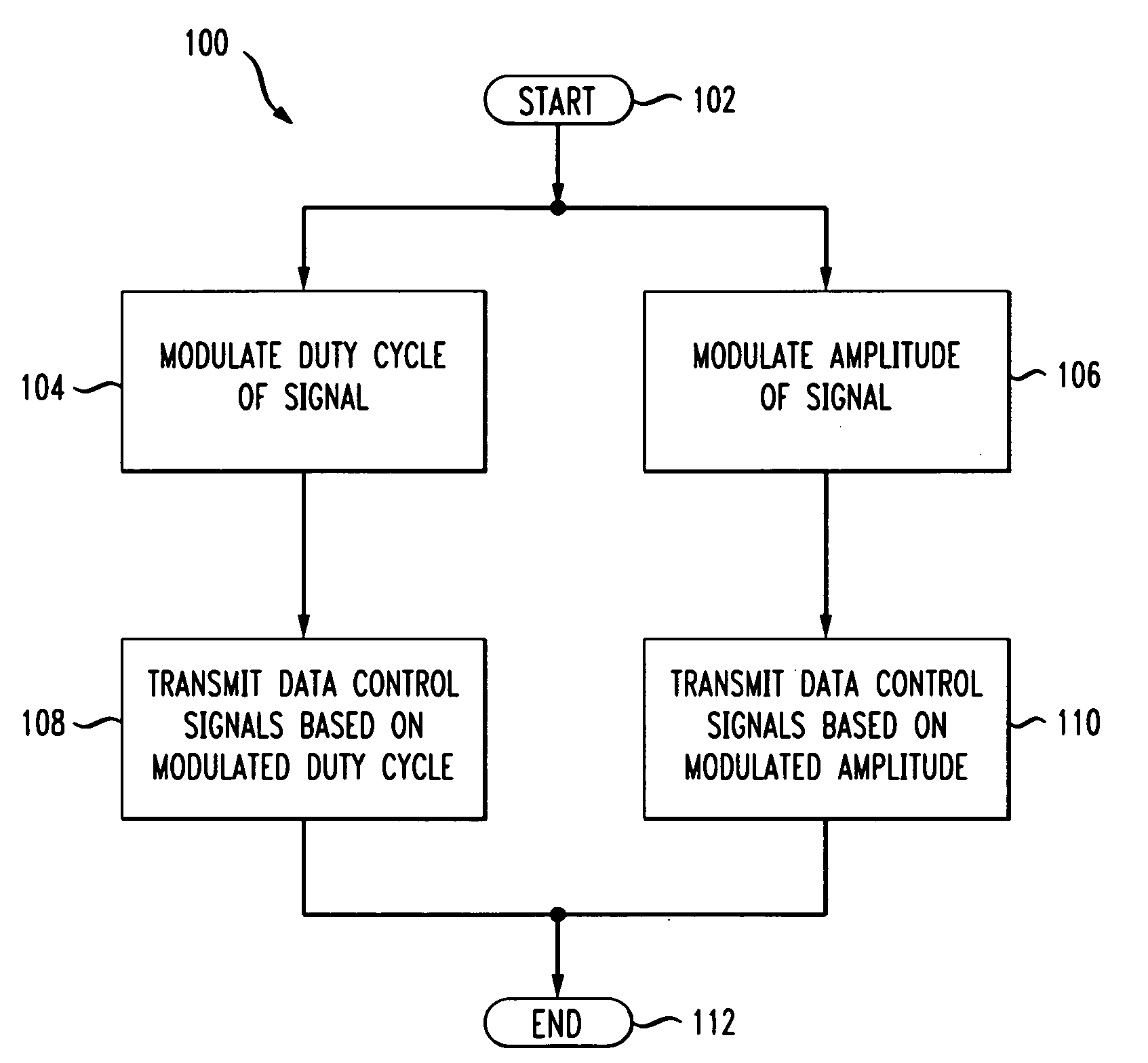
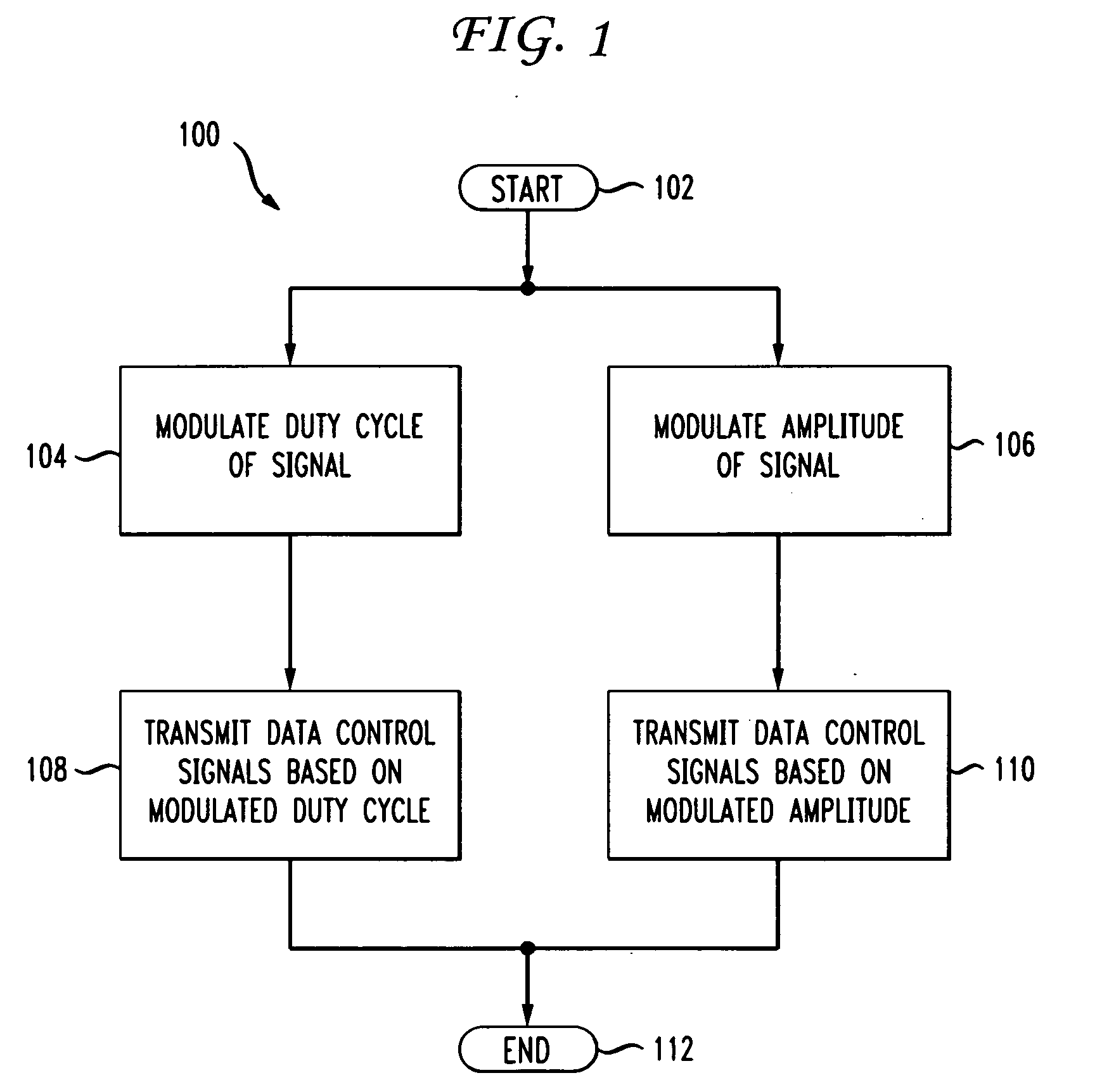
[0014]The present invention provides methods and apparatus for reducing jitter in serial transmissions. To reduce jitter, the duty cycle and amplitude of a signal are modified. The modification may include modulating the leading and trailing edges of a data pulse (e.g., a signaling bit of the signal) as well as leading and / or trailing edges of preceding and / or succeeding data pulses. Data control signals based on the modulated signals are sent to clock and data buffers to modulate the transmission and improve signal transmission.
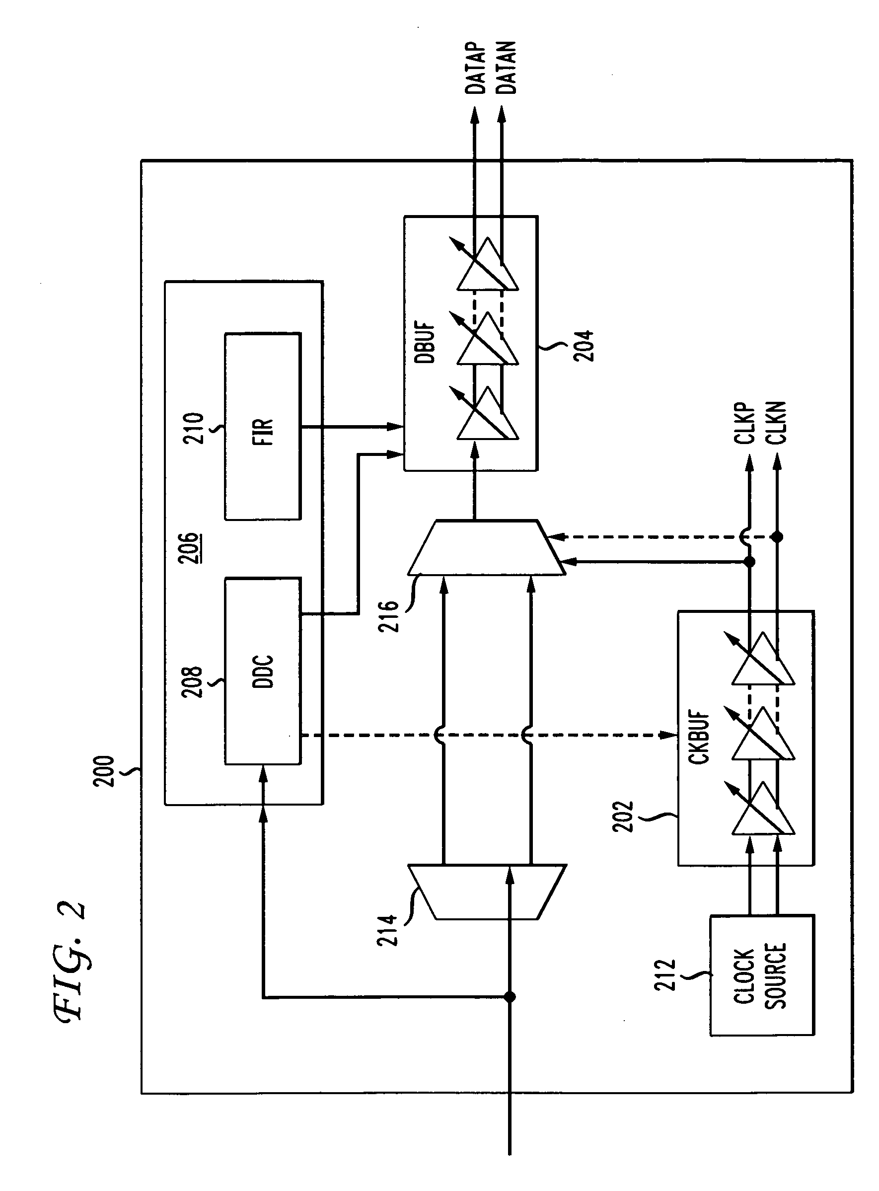
[0015]The signaling bit and / or other bits may be modulated using a multi-dimensional (e.g., a two-dimensional) modulation circuit. The modulation circuit includes a data dependency controller which modulates the pulse width of the signal. The modulation circuit also includes a circuit to modulate the amplitude of the signal. In this way, both the width and height of the data signal may be modulated and the transmission may be improved.

Problems solved by technology

Left uncompensated, DDJ will cause errors in the received data.
In a digital transmission system, such distortion of the received signal is manifested in the temporal spreading and consequent overlap of individual pulses to the degree that the receiver cannot reliably distinguish between changes of state (e.g., between individual signal elements).
ISI is usually an undesirable phenomenon as the surrounding symbols have a similar effect to noise, thus making the communication less reliable.
ISI will compromise the integrity of the received data.
DCD is generally generated within a SerDes device due to an imbalance in drive circuit bias levels.
This leads to increased power consumption.
Further, large signal swings also create voltage and current ripples and work as crosstalk aggressors.
Additionally, TXPE provides only limited DDJ compensation.
These clock delay elements are difficult to match and are difficult to control over process, temperature, and voltage.

Method used


Image

  • Method and apparatus for duty cycle pre-distortion and two-dimensional modulation
  • Method and apparatus for duty cycle pre-distortion and two-dimensional modulation
  • Method and apparatus for duty cycle pre-distortion and two-dimensional modulation

Examples


Embodiment Construction

[0032]The present invention relates generally to transmitter improvement and more particularly to duty cycle pre-distortion and two-dimensional modulation. Two-dimensional modulation incorporates an amplitude pre-emphasis scheme as well as a transmit duty cycle pre-distortion (pre-DCD) technique.

[0033]The inventive pre-DCD methods and circuits directly address transition edges of the data signal. Accordingly, it is a more efficient method of dealing with pulse width modulation (PWM) effects, especially PWM effects derived from optical systems. The pre-DCD method also reduces voltage and / or current swings. This minimizes strains on the power supply and reduces undesirable crosstalk effects.

[0034]Further, the present two-dimensional modulation method can use a TXPE circuit to approximate the inverse characteristics of the transmit data path. The two dimensional modulation may be configured to provide a filtering profile, FTX(f), mimicking the inverse of a channel profile, FChan(f), th...


PUM


Abstract

In serial communications, jitter is an unwanted variation of one or more signal characteristics. Two-dimensional modulation circuits and methods incorporate an amplitude pre-emphasis scheme as well as a transmit duty cycle pre-distortion (pre-DCD) technique to reduce jitter. The pre-DCD technique directly addresses transition edges of the data signal and is combined with amplitude pre-emphasis to improved data transmission.

Description

FIELD OF THE INVENTION[0001]The present invention relates generally to transmitter improvement and more particularly to duty cycle pre-distortion and two-dimensional modulation.BACKGROUND OF THE INVENTION[0002]In most modern communications protocols (e.g., in telecommunications), data is sent one bit at one time, sequentially, over a communications channel or computer bus as serial communications. In serial communications, jitter is an unwanted variation of one or more signal characteristics. Jitter may be seen in characteristics such as the interval between successive pulses, or the amplitude, frequency, or phase of successive cycles. Jitter is a significant factor in the design of almost all communications links (e.g., USB, PCI-e, SAS / SATA, XAUI, Infiniband, SONET / SDH, FC, etc.). Jitter is found in a number of signal characteristics (e.g., amplitude, phase, pulse width, or pulse position), and can be quantified in the same terms as all time-varying signals (e.g., root mean square ...

Claims


Application Information

Patent Timeline
IPC IPC(8): H04L7/00H04L25/40
CPCH04L25/4902
Inventor ZHANG, GEOFFREYDAI, XINGDONG
Owner AVAGO TECH INT SALES PTE LTD
Learn More