
Sandwiich panel for sound absorption

a technology for aircraft cabins and sandwiches, which is applied in the direction of liquid fuel engines, instruments, machines/engines, etc., can solve the problems of loss within the perforation opening, composite panels are far too heavy for aircraft use, and panels that are too heavy for large-area use, etc., to achieve precise and simple production of perforations, reduce weight, and facilitate production

Active Publication Date: 2009-07-02
AIRBUS OPERATIONS GMBH
View PDF22 Cites 36 Cited by
  • Summary
  • Abstract
  • Description
  • Claims
  • Application Information

AI Technical Summary

Benefits of technology

The invention is about a new type of acoustic panel for use in aircraft cabins that improves sound absorption. The panel has a core layer with a honeycomb-like structure made up of cells separated by cell walls. The cell walls have small openings that create a resonator that dampens out the sound waves. The panel also has a second cover layer that is perforated with small holes. The distance between the holes is larger than the thickness of the panel, which results in a larger hollow space volume and a lower resonance frequency. This design allows for improved sound absorption and damping, and is lightweight and easy to install.

Problems solved by technology

The damping that is decisive to the broad bandwidth of the achievable absorption results from losses that occur within the perforation opening at resonance.
However, these composite panels are far too heavy for the use in aircraft.
However, the proposed solutions are not suitable for use in the cabin interior, because there is insufficient space for installation, and furthermore because such a design results in panels that are too heavy for large-area use in the interior of aircraft cabins.
Furthermore, known sound-absorbing sandwich panels with a honeycomb core are associated with a disadvantage in that the cell walls of the honeycomb structure limit the volume of the hollow spaces.

Method used


Image

  • Sandwiich panel for sound absorption
  • Sandwiich panel for sound absorption
  • Sandwiich panel for sound absorption

Examples


Embodiment Construction

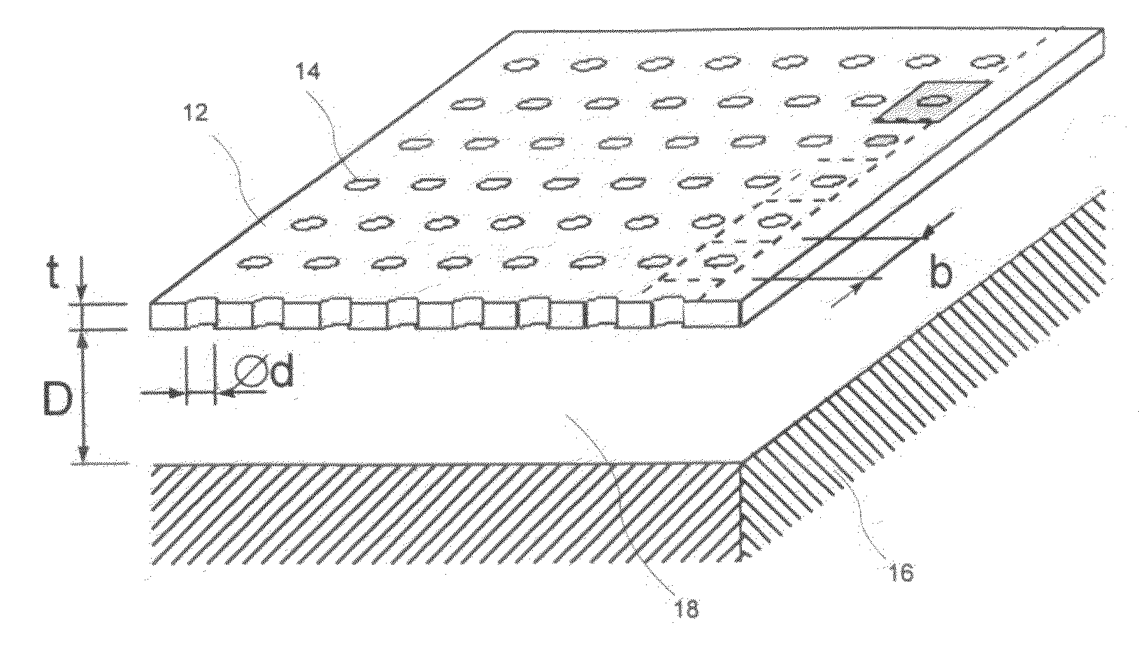
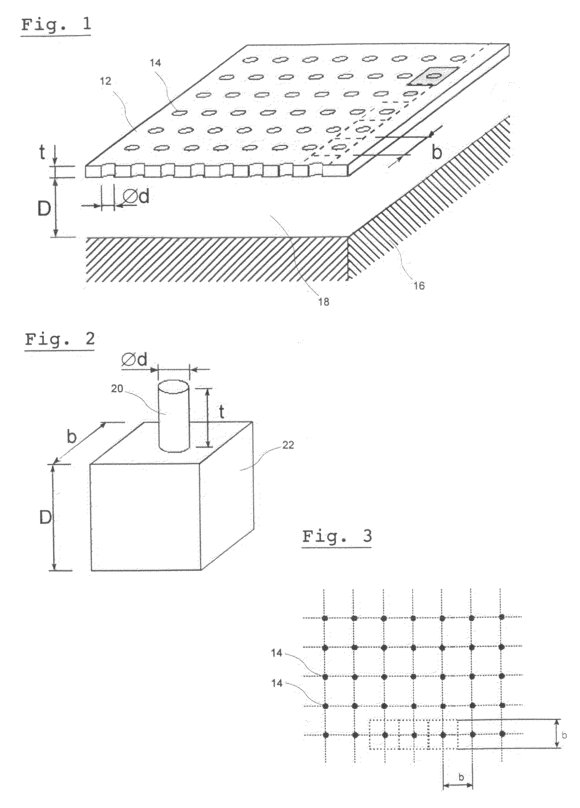
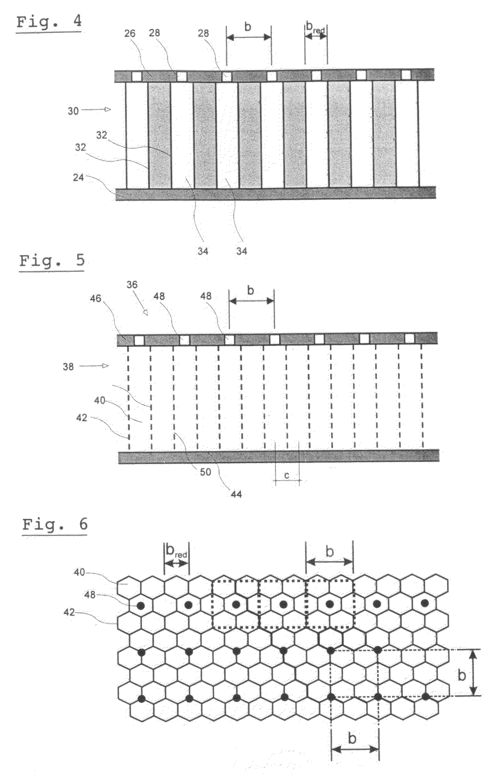
[0025]FIG. 1 shows the principle design of a perforated liner resonator that comprises a perforated liner 12 which comprises a multitude of holes 14. The perforated liner 12 of a thickness t is arranged at a distance D in front of a rear delimitation area 16 so that an air volume 18 is enclosed between the perforated liner 12 and the delimitation area 16. In order to consider the way of operation of the perforated liner resonator, said resonator can also be considered to be an addition of several Helmholtz resonators. FIG. 2 shows the basic structure of a Helmholtz resonator with the four geometric parameters hole diameter d, distance between holes b, liner thickness t and thickness of the air cushion D. The Helmholtz resonator, which in FIG. 2 is shown without the volume-delimiting components, represents an acoustic resonator, which can also be regarded as a spring-mass damping system, comprising an air plug 20 in the region of the aperture 14 of the perforated liner 12, and a perc...


PUM


Abstract

An aircraft cabin panel for sound absorption, with a sandwich construction, comprising a core layer that comprises a plurality of tube-like or honeycomb-like cells that extend in an open manner across the thickness of the core layer and that are separated from each other by cell walls and that are uniform in design. A first cover layer faces away from the sound field, as well as a second cover layer that faces towards the sound field and that comprises a plurality of perforation holes and adjacent cells are interconnected by way of apertures in the cell walls. The perforation of the second cover layer comprises a distance (b) between holes, which distance exceeds the opening width (c) of the cells of the core layer, wherein the first cover layer is closed and wherein the cell walls comprise a perforation so that they are acoustically transparent in the direction parallel to the cover layers.

Description

CROSS-REFERENCE TO RELATED APPLICATIONS[0001]This application claims the benefit of the filing date of U.S. Provisional Patent Application No. 61 / 007,878 filed Dec. 17, 2007, the disclosure of which is hereby incorporated herein by reference.BACKGROUND OF THE INVENTION[0002]The present invention relates to an aircraft cabin panel for sound absorption. The invention in particular also relates to a device for sound absorption in an aircraft cabin.[0003]Acoustic panels are used in rooms in order to improve the acoustic characteristics of the room, in that the sound that is perceived to be disturbing is absorbed by the panels, e.g. in aircraft cabins. As the demand for greater comfort in rooms generally increases, at the same time there is a parallel demand for improved conditions of travel in aircraft, among other things also relating to room acoustics during flight operation. To this effect it is desirable to use sandwich panels for sound absorption in the interior of aircraft cabins ...

Claims


Application Information

Patent Timeline
Patent Type & Authority Applications(United States)
IPC IPC(8): E04B1/82
CPCB64C1/40Y02T50/46G10K11/172Y02T50/40
Inventor THOMAS, CHRISTIANGERSTNER, RALPH
Owner AIRBUS OPERATIONS GMBH
Learn More