
Universal routing in pci-express fabrics

Active Publication Date: 2009-06-25
SANDISK TECH LLC
View PDF6 Cites 89 Cited by
  • Summary
  • Abstract
  • Description
  • Claims
  • Application Information

AI Technical Summary

Benefits of technology

[0027]The switch has a data processing unit, e.g., a network processor, that handles exceptions in case of missed lookups due to errors in packets or other protocol mismatches. The data processing unit also verifies the validity of the source ID for the source port. The data processing unit may also check that the source ID has permission to route the packets to the destination port. The data processing unit may contain internal memory or external memory modules such as SRAM, DRAM, and uses software algorithms for comparing and verifying URIDs. The URID comparison could also be implemented in hardware such as content addressable memory (CAM) for achieving high performance.
[0030]It is an advantage of at least one embodiment of the present invention that all features related to the URID capabilities can be individually enabled or disabled under software control.
[0031]It is yet another advantage of at least one embodiment of the present invention that bridges and switches can be configured to route transaction packets to tens of thousands single function devices.
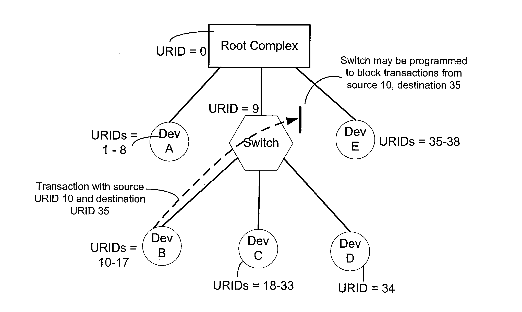
[0032]It is yet another advantage of at least one embodiment of the present invention to provide a lookup table so that a switch or bridge can be configured to have packet filtering and port blocking capability.

Problems solved by technology

This architecture severely limits the number of devices that can exist in a PCI subsystem.
Non-transparent bridges add expense and complication to the PCIe system and require higher layer applications to properly complete discovery and enumeration of a system.
The disadvantage is that the number of buses supported in the system is still a restriction in many PCI-Express architectures.
As the PCIe is a point-to-point connection, device numbers used previously in a PCI bus to identify the addressed device coupled to a PCI bus are not really useful anymore.

Method used


Image

  • Universal routing in pci-express fabrics
  • Universal routing in pci-express fabrics
  • Universal routing in pci-express fabrics

Examples


Embodiment Construction

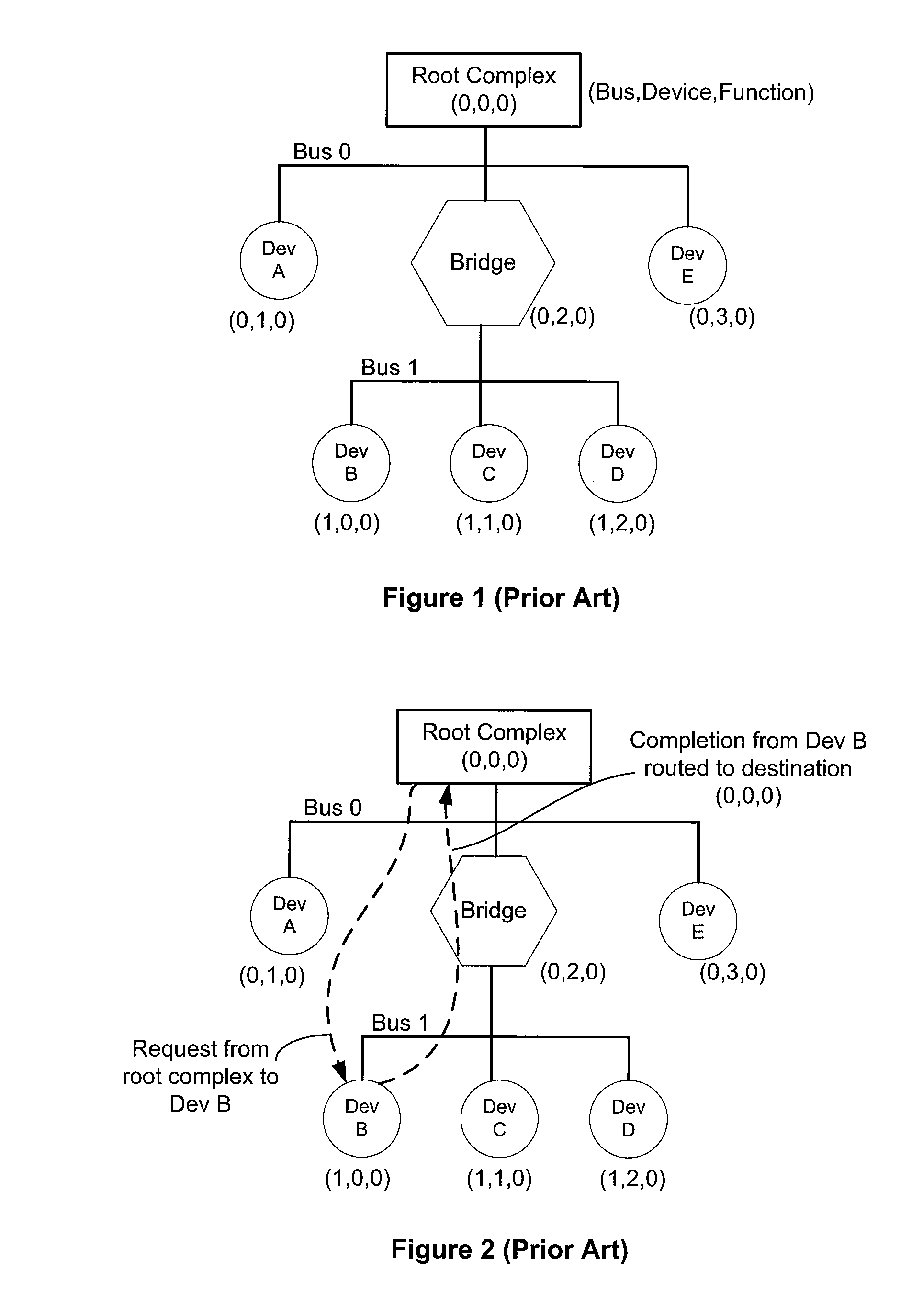
[0042]The root complex (RC) initializes with a bus number, device number and function number (BDF) that are used to form a requester ID or completer ID. The RC BDF initializes to all 0s. FIG. 2 shows that the root complex (the requester) originates a request transaction to the destination device B which is the completer. The RC inserts the 16-bit requester (source) ID and the BDF (1,0,0) of the target device in the header of the transaction layer packet. Upon receipt of the request transaction packet, the bridge (0,2,0) compares the destination bus number in the packet header to the range of buses that reside downstream of the bridge. If the bus destination number is downstream of the bridge (Bus 1 in this example), the packet will pass through. Devices coupled to Bus 1 compare the device number and the one that finds a match will accept the packet. Functions (a maximum of eight) on the destination device compare the function number in the header of the packet. The function addresse...


PUM


Abstract

A universal routing identifier (URID) is provided to extend the function space in PCI-Express fabrics. Methods and systems based on the URID are provided for configuring URID capable devices and upgrading PCI-Express bridges and switches having lookup tables with access control functionality. The lookup table entry contains URIDs of destination ports, backup ports, acceptance ports, and permitted ports for downstream and upstream filtering, routing and arbitrating of transaction packets. URID capable devices can be incrementally added to current PCI-Express bridges and switches. A configuration mechanism is added to the current PCI / PCI-Express enumeration software. The URID capabilities can be disabled to maintain system compatibility. A URID capable PCI-Express system is able to address ten of thousands single-function devices. A URID capability segment field is provided in the current PCI-Express configuration space. Each URID capable device contains the URID capability segment implemented in its own set of configuration space registers.

Description

CROSS-REFERENCES TO RELATED APPLICATIONS[0001]Not ApplicableSTATEMENT AS TO RIGHTS TO INVENTIONS MADE UNDER FEDERALLY SPONSORED RESEARCH OR DEVELOPMENT[0002]Not ApplicableREFERENCE TO A “SEQUENCE LISTING,” A TABLE, OR A COMPUTER PROGRAM LISTING APPENDIX SUBMITTED ON A COMPACT DISK.[0003]Not ApplicableBACKGROUND OF THE INVENTION[0004]A standard Peripheral Component Interconnect (PCI) bus is generally known as a local parallel bus that allows expansion cards to be added into a single computer system. Examples of commercially available expansion cards with PCI bus interface are SCSI (data storage) cards, wireless LAN add-in cards, analog and digital TV tuner add-in cards, USB and FireWire controllers, Gigabit Ethernet add-in cards, etc. The PCI bus communicates with a single CPU or multiple CPUs of the computer system through a PCI-bridge controller. Several PCI bridges may exist in a computer system and couple a diversity of input / output (IO) devices to the multiple CPUs of the comput...

Claims


Application Information

Patent Timeline
IPC IPC(8): G06F3/00
CPCG06F13/4022
Inventor TALAYCO, DANIELAKYOL, BORAEKICI, ALI
Owner SANDISK TECH LLC
Learn More