Circular-Shank Tool Comprising a Tool Holder

Active Publication Date: 2009-06-25
BETEK BERGBAU UND HARTMETALLTECHN KARL HEINZ SIMON
View PDF12 Cites 3 Cited by
  • Summary
  • Abstract
  • Description
  • Claims
  • Application Information

AI Technical Summary

Benefits of technology

[0006]It is one object of this invention to provide holding elements of the clamping sleeve of a round shank chisel with a chisel holder of the type mentioned above but in such a way that they reduce the axial play, and to improve the centering of the shank in the clamping sleeve so that the shank can rotate without hindrance in the clamping sleeve.
[0008]Matching the width of the holding elements to the width of the circumferential groove in the shank of the round shank chisel results in the reduction of axial play between the clamping sleeve and the shank, while the holding elements with coaxial, concave centering sections facing the convex groove bottom optimize the function of the round shank chisel with a chisel holder.
[0011]The critical point of the clamping sleeve is located on the side of the front face of the clamping sleeve facing the chisel tip. For preventing collisions with this front face, which can lead to an impairment of the rotating movements of the round shank chisel, in one embodiment the front face of the clamping sleeve facing the chisel tip is at a distance from the conical insertion section of the bore in the chisel holder, which receives a conical neck of the chisel head or a centering neck of a wear disk arranged between the chisel holder and the chisel head.

Problems solved by technology

Also, the holding elements in the circumferential groove of the shank of the round shank chisel do not provide sufficient guide faces for an unequivocal centering of the shank, because of which rotating movement in the clamping sleeve is hampered.

Method used


Image

  • Circular-Shank Tool Comprising a Tool Holder
  • Circular-Shank Tool Comprising a Tool Holder
  • Circular-Shank Tool Comprising a Tool Holder

Examples


Embodiment Construction

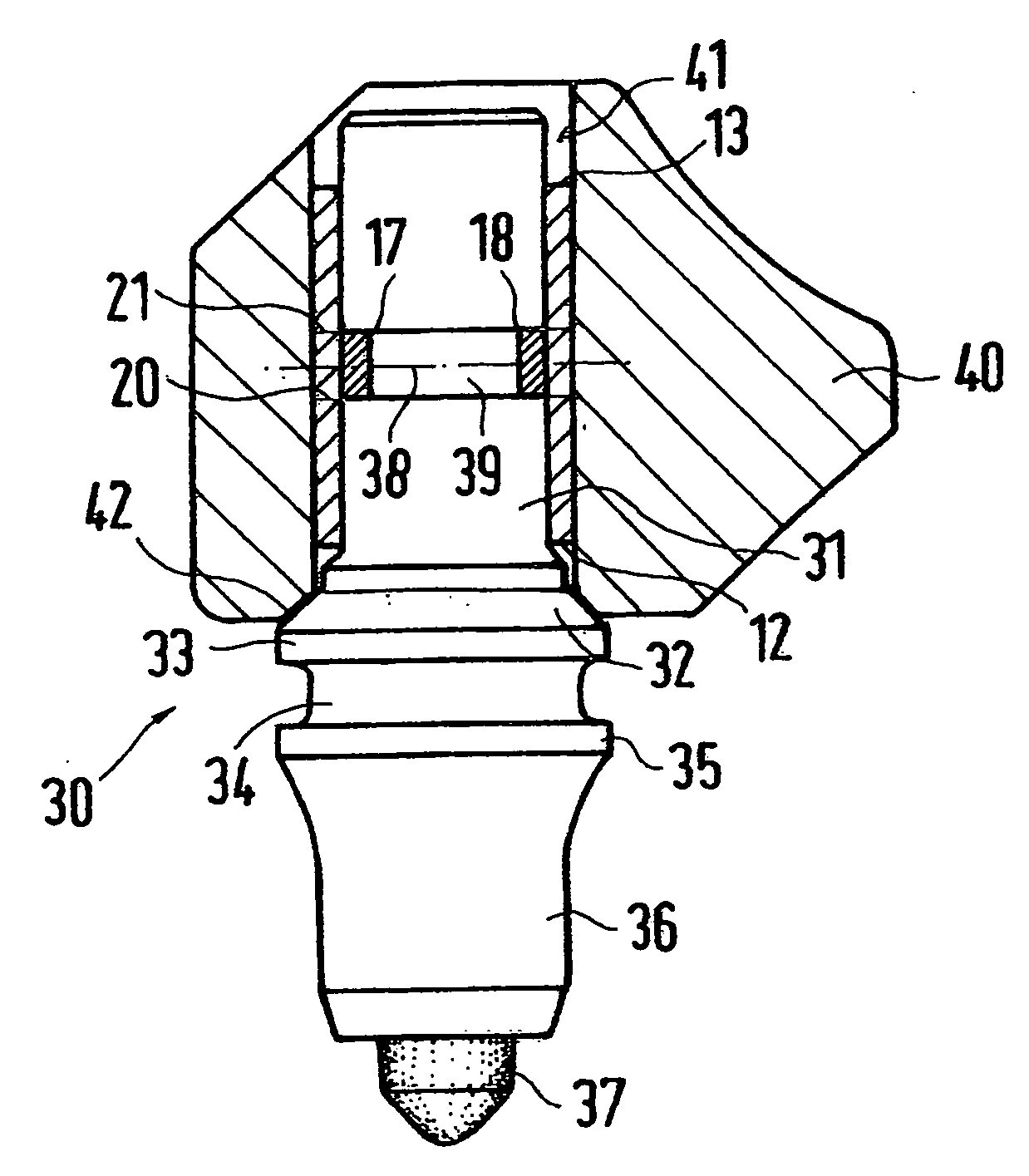
[0019]As FIGS. 1 to 3 shows, the clamping sleeve 10 has a slit 11 parallel with the longitudinal axis 19, and three holding elements 16, 17, 18 are distributed over the circumference. The holding element 16 is located opposite the slit 11. The two other holding elements 17 and 18 are each offset on the circumference of the clamping sleeve 10 with respect to the holding element 16 by approximately α=100°. The holding elements 16, 17, 18 are respectively spaced apart by two parallel punched edges 20 and 21, which are oriented transversely with respect to the longitudinal axis 19 and extend over an angular panel of approximately 30°0 to 50° of the circumference.

[0020]In their width, the holding elements 16, 17 and 18 are defined by the distance of the punched edges 20 and 21 and are matched to the width of the circumferential groove 39 in the shank 31 of the round shank chisel 30.

[0021]At their ends, the concave centering sections 22 of the holding elements 16, 17 and 18 transition int...


PUM


Abstract

A circular-shank tool including a tool holder for improving the centering of the shank of the circular-shank tool in the locking sleeve by a configuration of the retaining elements and to improve an ability of the shank to rotate in the sleeve. To achieve this, the retaining elements are distributed between two stamped edges that lie transversely with respect to a longitudinal axis of the locking sleeve and are stamped inwards or indented, the stamped edges extend over part of the circumference of the locking sleeve and are interspaced at a distance that corresponds to the width of the peripheral groove in the shank of the circular-shank tool and the retaining elements form a coaxial concave centering section facing the convex groove base of the peripheral groove.

Description

BACKGROUND OF THE INVENTION[0001]1. Field of the Invention[0002]This invention relates to a round shank chisel with a chisel holder, in which a shank of the round shank chisel holder is maintained in the bore of the chisel holder by a slit clamping sleeve, wherein the clamping sleeve is braced against the bore wall of the bore and the shank of the round shank chisel is rotatably maintained in the clamping sleeve, wherein the clamping sleeve has inwardly machined in and / or pressed in holding elements that distributed over a circumference of the clamping sleeve and that engage a circumferential groove cut into the shank of the round shank chisel, so that the clamping sleeve is fixed in place on the shank of the round shank chisel so that it cannot be shifted.[0003]2. Discussion of Related Art[0004]In connection with a round shank chisel with a chisel holder, the axial position of the clamping sleeve on the shank of the round shank chisel is important, so that the front faces of the cl...

Claims


Application Information

Patent Timeline
IPC IPC(8): E21C35/197
CPCE21C35/197
Inventor KAMMERER, KARL
Owner BETEK BERGBAU UND HARTMETALLTECHN KARL HEINZ SIMON
Why Eureka
Try Eureka