Centrifugal Switching Device of Single-Phase Induction Motor

a technology of induction motor and centrifugal switching, which is applied in the direction of dynamo-electric converter control, starter details, dynamo-electric components, etc., can solve the problem of inability to achieve the stated functions, and achieve the effect of effectively overcoming the defects of the conventional art and smooth rotation without making any nois

Active Publication Date: 2009-06-25
HUAN YIJUN
View PDF4 Cites 4 Cited by
  • Summary
  • Abstract
  • Description
  • Claims
  • Application Information

AI Technical Summary

Benefits of technology

[0019]Accordingly, the present invention is directed to a centrifugal switch driving device of a single-phase induction motor, which may effectively overcome the defects in the conventional art. The centrifugal switching device of a single-phase induction motor provided by the present invention includes a centrifugal sleeve, a centrifugal base, a shaft coupling block I, a shaft coupling block II, a spring, and pressure switches. The present invention is characterized in that: the shaft coupling blocks are designed to be coupled through a straight pin, and have a smooth rotation without making any noise; the shaft coupling blocks I and II are designed to slide axially to prevent the centrifugal switch from being easily damaged; the spring is directly fitted on an outer cylindrical surface of the centrifugal base, the centrifugal sleeve moves axially under a uniform force exerted by the spring; and an axial end surface of the centrifugal sleeve transiently releases contacts of the pressure switches.
[0022]2. The spring (12) in the conventional centrifugal switch operates in the radial direction of the spindle (10), such that the centrifugal sleeve (16) suffers a non-uniform force. However, the spring (12) in the present invention is directly fitted on the centrifugal base (17), and operates in the axial direction of the spindle (10), thus having a simple and practical structure.
[0023]3. The centrifugal hammer of the conventional centrifuge has to be mounted passing through a slide bar and engaged with the spring, so the fabrication and assembling processes are difficult. On the contrary, the spring in the present invention is directly fitted on the centrifugal base, and the shaft couplers 1 and 2 are mounted through a pin, which is rather simple and convenient.

Problems solved by technology

Thereby, after a long time of operation, the centrifugal sleeve will be abraded and separated from the centrifugal hammer, and thus the stated functions cannot be achieved.

Method used


Image

  • Centrifugal Switching Device of Single-Phase Induction Motor
  • Centrifugal Switching Device of Single-Phase Induction Motor
  • Centrifugal Switching Device of Single-Phase Induction Motor

Examples


Embodiment Construction

[0037]The present invention will be further illustrated below with the accompanying drawings.

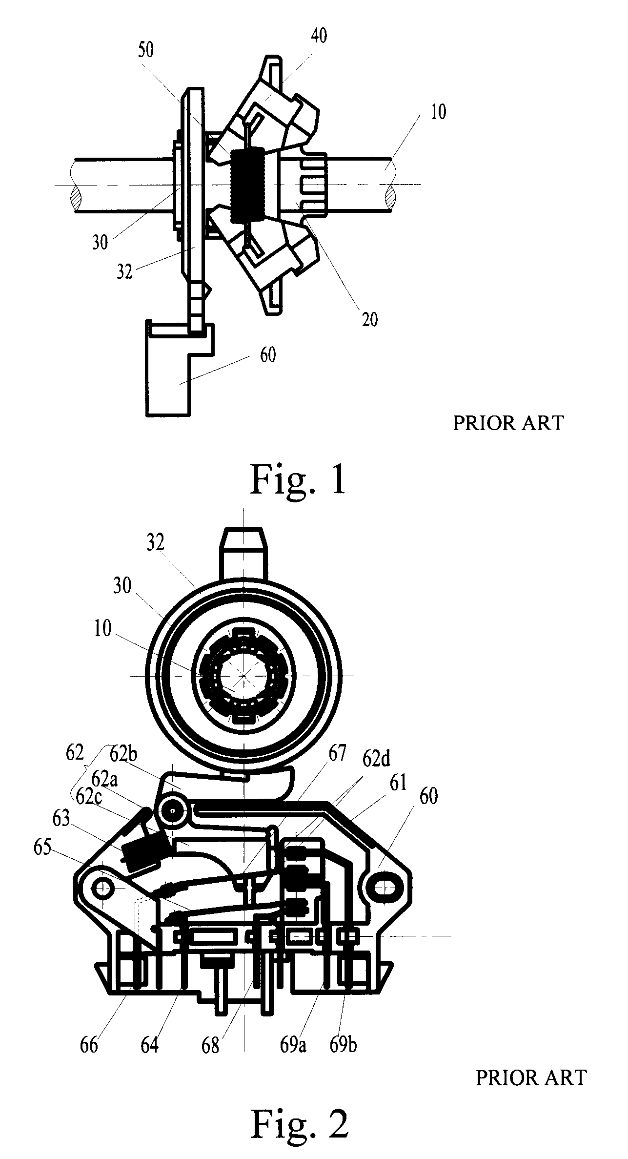
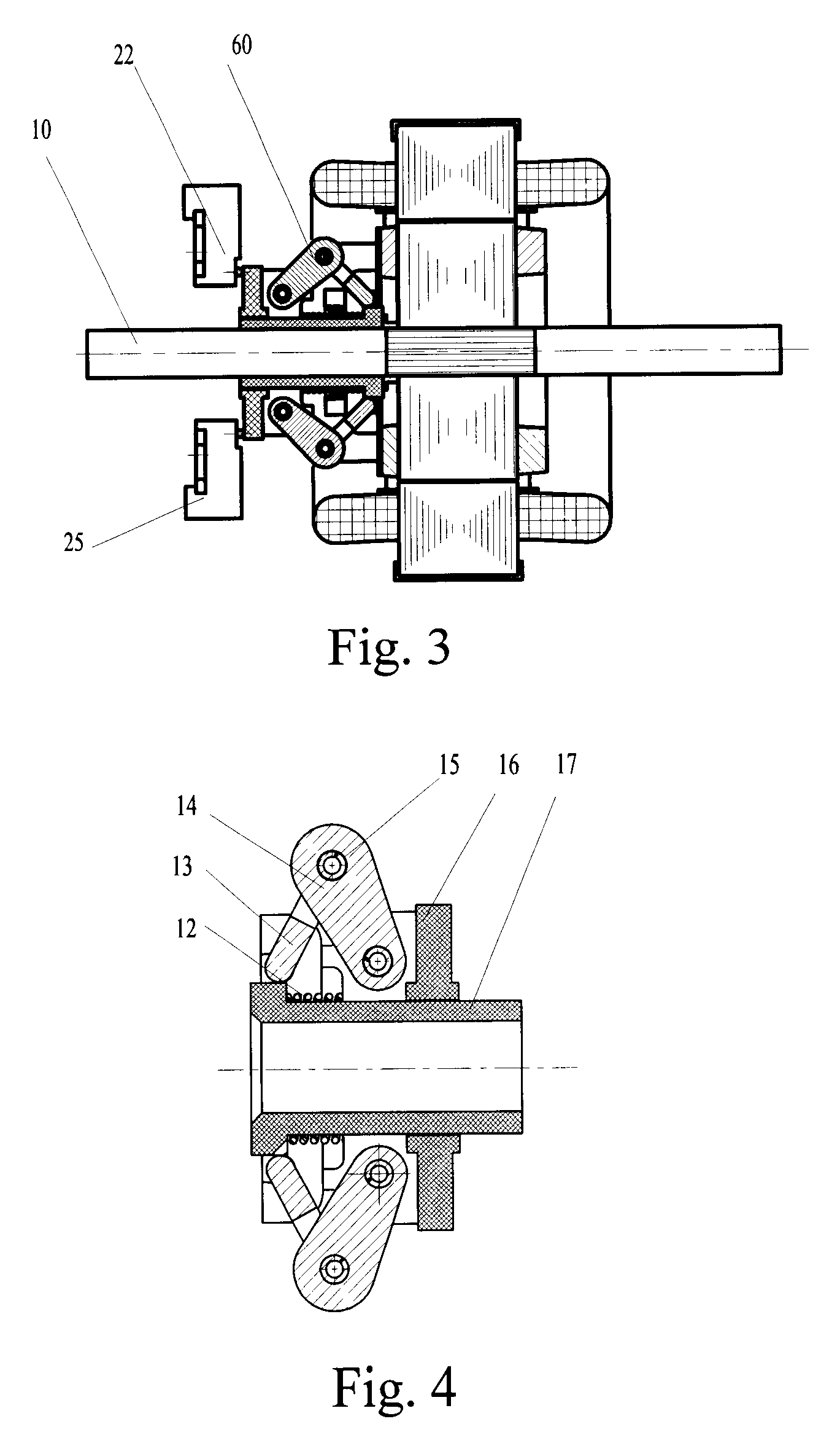
[0038]Referring to FIGS. 3 and 4, a single-phase induction motor includes a centrifugal switch (60), a winding pressure switch (22), a heater pressure switch (25), and a spindle (10). Under the centrifugal force generated by rotation, the centrifugal sleeve (16) rotating together with the spindle of the motor makes the shaft coupling block I (13) and the shaft coupling block II (14) slide in an axial direction of the spindle, so as to be separated from the winding pressure switch (22) to disconnect the starting winding enwinding the single-phase induction motor, and to be separated from the heater pressure switch (25) to turn on the heater. When the rotating speed is lowered, the centrifugal sleeve (16) is restored by the force of a spring. The spring (12) in the conventional centrifugal switch operates in the radial direction of the spindle (10), such that the centrifugal sleeve (16) suffer...


PUM


Abstract

A centrifugal switching device of a single-phase induction motor includes a centrifuge and pressure switches. The centrifuge includes a centrifugal sleeve, a centrifugal base, shaft coupling blocks, and a spring. The spring is directly fitted on the centrifugal base. Under a centrifugal force generated by the rotation of the motor, shaft coupling blocks I and II slide axially against an axial force of the spring, thus forcing an axial end surface of the centrifugal sleeve to be separated from contacts of the pressure switches, such that a starting winding of a stator ferrite-core coil of the single-phase induction motor is disconnected and a heater is turned on. The shaft coupling blocks I and II adopt a design with round transition, central sliding contact, and smooth rotation, thereby achieving a simple structure, convenient mounting, and safety usage.

Description

CROSS REFERENCE TO RELATED PATENT APPLICATION[0001]This patent application claims the priority of the Chinese patent application No. 200710191471.5 filed on Dec. 19, 2007, which is incorporated herein by reference.BACKGROUND OF THE INVENTION[0002]1. Field of Invention[0003]The present invention relates to a centrifugal switching device of a single-phase induction motor.[0004]2. Related Art[0005]Since single-phase induction motor has a simple but firm structure, and a single-phase power supply can be easily found, the single-phase induction motor serving as a driving motor for electrical appliances is widely applied in family, office, industry, and agriculture. However, the motor cannot activate automatically. Therefore, in order to generate a starting torque, besides an operating winding, a starting winding having a phase difference with the operating winding should be further provided.[0006]When the rotating speed of a rotator reaches 70%-80% of the synchronous speed, a centrifugal...

Claims


Application Information

Patent Timeline
Patent Type & Authority Applications(United States)
IPC IPC(8): H01H35/10
CPCH01H35/10H02P25/182H02P1/42H02K11/0036H02K11/23
Inventor HUAN, JIANBINZHENG, ZIMINGSU, SHENKEXIONG, FENGTANG, ZHENDONGLI, XIANGZHILU, JIANSONG
Owner HUAN YIJUN
Why Eureka
Try Eureka