
Load sharing interbody fusion device

a fusion device and load-sharing technology, applied in the field of intervertebral fusion devices, can solve the problems of devices that cannot be fusioned under the high load of the spine, the rigidity of the spacer does not allow load-sharing with a bone, and the strength of materials is limited

Inactive Publication Date: 2009-06-18
INTELLIGENT IMPLANT SYST
View PDF4 Cites 36 Cited by
  • Summary
  • Abstract
  • Description
  • Claims
  • Application Information

AI Technical Summary

Benefits of technology

"The present invention provides an interbody fusion device that can be used to space apart and fuse together adjacent vertebral surfaces. The device includes a body that is implanted between the vertebral surfaces and a bone graft load sharing system that distributes the load between the body and the bone graft material. The invention also provides a method for controlling the reduction and height of the spacer during the healing process of a reconstructed vertebral space. Additionally, the invention includes piston means for entrapping a bioresorbable material and a method for remodeling vertebral bone by containing a column of bone graft material in a body member having a reducable height."

Problems solved by technology

The most significant problem of the aforementioned conventional intervertebral body spacers is that the rigidity of the spacer does not allow for load sharing with a bone graft or bone substitute.
Another problem with conventional spacers that are made from bioresorbable materials, such as poly-L-lactides (PLLA), is that these materials have limited strength and are designed to resorb completely away.
With limited strength, these devices can fracture under the high loads of the spine.
If fusion does not take place and the bioresorbable materials resorb, the space established during surgery closes and the preoperative painful condition returns.
While the aforementioned devices can be suitable for a particular purpose to which they address, they are not as suitable to providing a device that permits load sharing with the bone graft or bone substitute material while providing sufficiently rigid support of the spine during a healing process.

Method used


Image

  • Load sharing interbody fusion device
  • Load sharing interbody fusion device
  • Load sharing interbody fusion device

Examples


Embodiment Construction

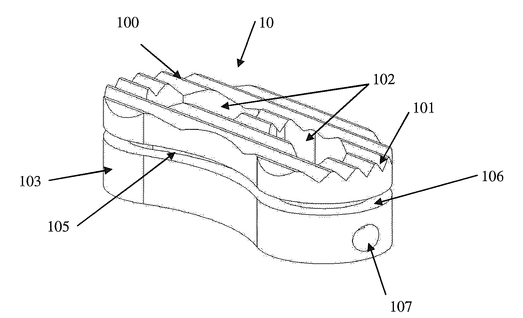
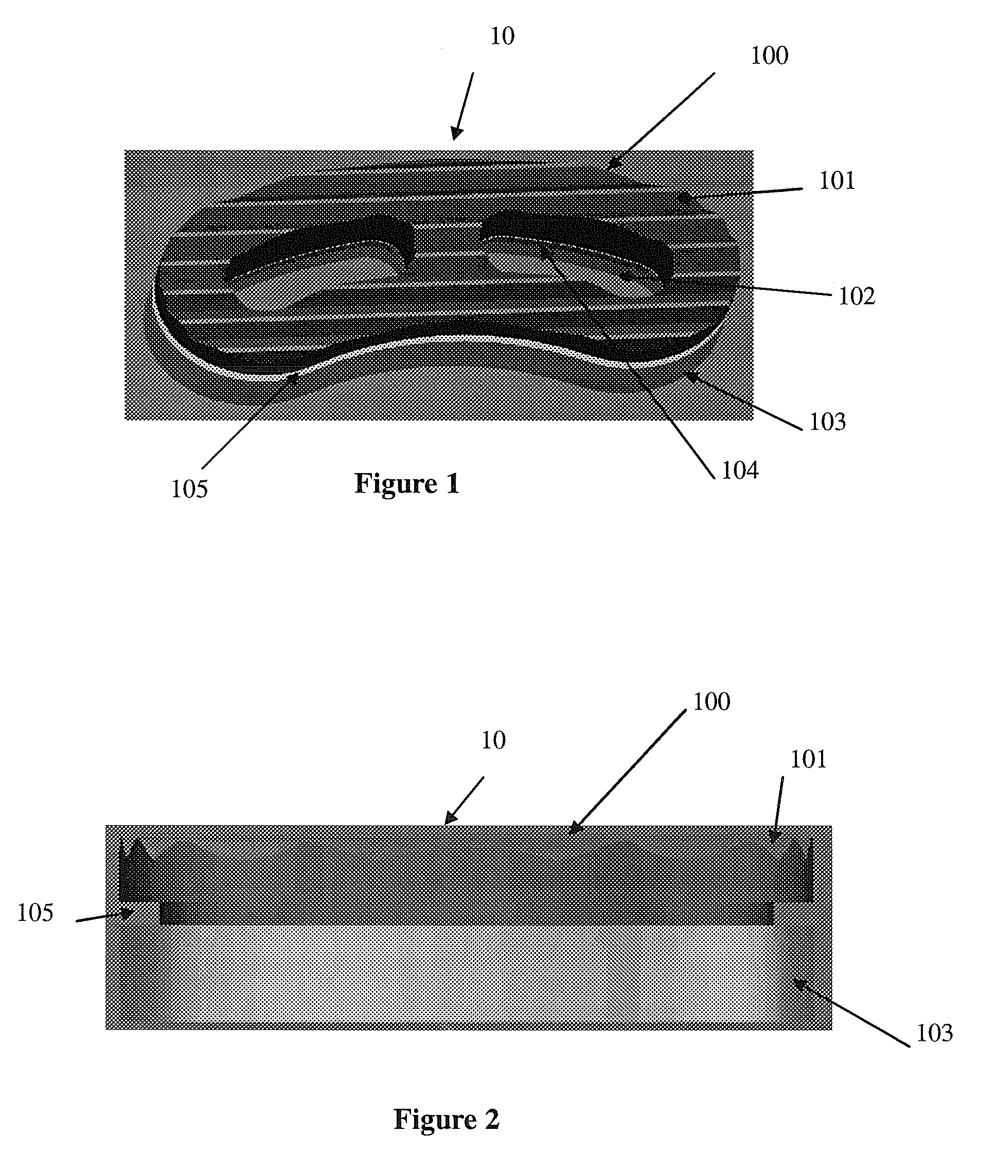
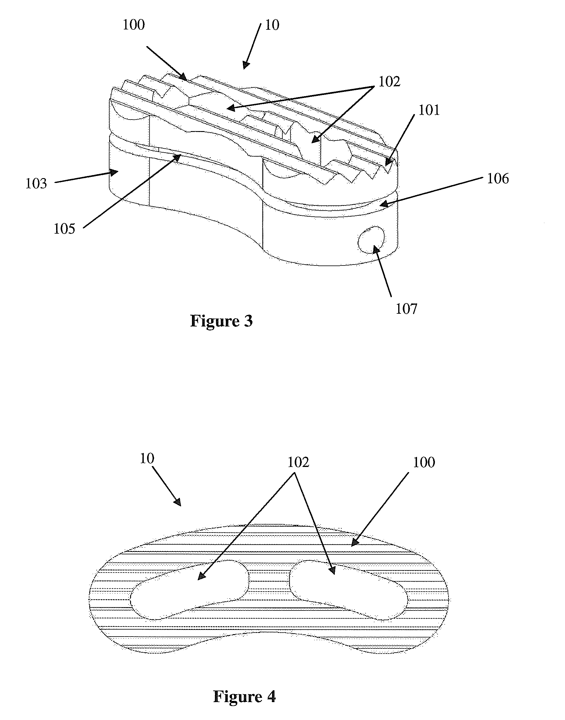
[0034]An interbody fusion device made in accordance with the present invention is generally shown at 10 in the Figures. The device 10 generally includes an upper body section 100 which moves relative to a lower body section 103. Together, the upper and lower body sections 100, 103 provide a body mechanism for spacing apart opposing vertebral surfaces when the body mechanism is implanted therebetween. The invention is characterized by including a bone graft load sharing mechanism for sharing loads, placed on the body portions 100, 103 by the opposing vertebral surfaces, the loads being shared between the body portions 100, 103 and bone graft material contained by the body portions 100, 103. That is, loads are placed on the device 10 by the surrounding vertebral end plates that define the intervertebral space into which the device 10 is surgically placed. In prior art devices, the loads placed on the device would be totally isolated from any bone graft material contained therein. The ...


PUM

PropertyMeasurementUnit
heightaaaaaaaaaa
resorbableaaaaaaaaaa
bioresorbableaaaaaaaaaa

Abstract

The present invention is a load sharing intervertebral fusion device that allows for reconstruction of the proper disc space between two vertebral bodies while allowing bone material packed within the fusion device to share loading and stress for enhanced healing. The device includes two sections, an upper and lower section, separated by a bioresorbable spacer. The upper section slides relative to the lower section with the bioresorbable material being placed in load therebetween. The upper section and lower sections are effectively held apart, creating an initial fixed spacer for implantation of the intervertebral disc space. Openings in the implant construct allow for bone graft and bone substitutes to be placed within the implant to allow for fusion through the implant construct. After implantation and over a period of time based on bone resorbtion and remodeling, the spacer resorbs, thereby maintaining load on the bone graft material.

Description

CROSS-REFERENCE TO RELATED APPLICATIONS[0001]This application claims the benefit of priority to U.S. Provisional Ser. No. 61 / 007,385, filed Dec. 12, 2008, which is incorporated herein by reference.TECHNICAL FIELD[0002]The present invention relates generally to intervertebral fusion devices, and more specifically it relates to a load sharing intervertebral fusion device which assists in fusing two vertebrae.BACKGROUND OF THE INVENTION[0003]Intervertebral body spacers have been in use for many years. Typically, these spacers are constructed from polymers, such as polyetherether ketone (PEEK) polymer, titanium, and stainless steels. By inserting these devices into a disc space, restoration of the disc space height is reestablished. The device removes pressure on nerve structures and eliminates nerve entrapment caused by the otherwise collapsed disc space. More recently developed devices, constructed of polymers or composites, provide an additional benefit of being radiolucent when view...

Claims


Application Information

Patent Timeline
Patent Type & Authority Applications(United States)
IPC IPC(8): A61F2/44
CPCA61F2/4455A61F2002/449A61F2/447A61F2002/2835A61F2002/286A61F2002/30062A61F2002/30556A61F2002/30601A61F2002/30672A61F2002/30772A61F2002/30904A61F2210/0004A61F2250/0009A61F2250/0059A61F2002/30607A61F2002/30616A61F2/4465
Inventor RICHELSOPH, MARC E.
Owner INTELLIGENT IMPLANT SYST
Learn More