Endoscope apparatus
- Summary
- Abstract
- Description
- Claims
- Application Information
AI Technical Summary
Benefits of technology
Problems solved by technology
Method used
Image
Examples
first embodiment
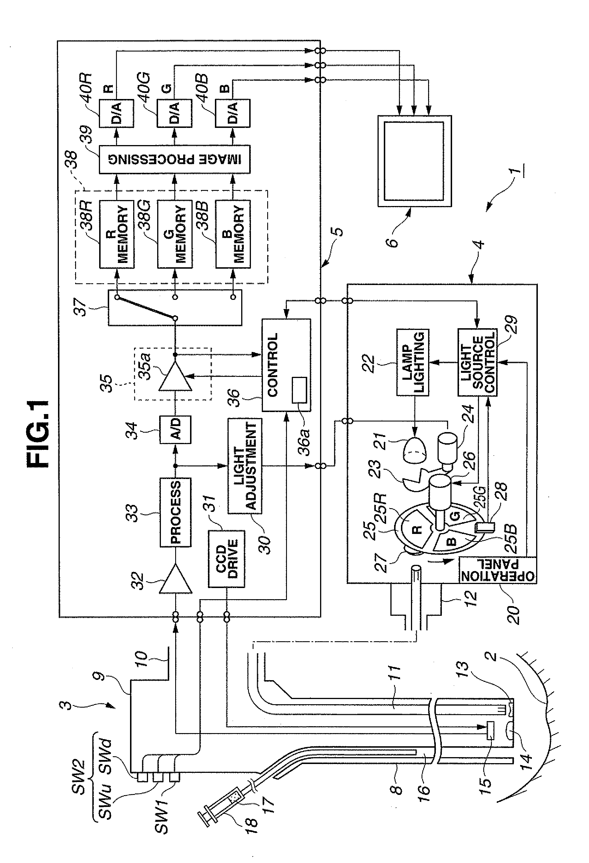
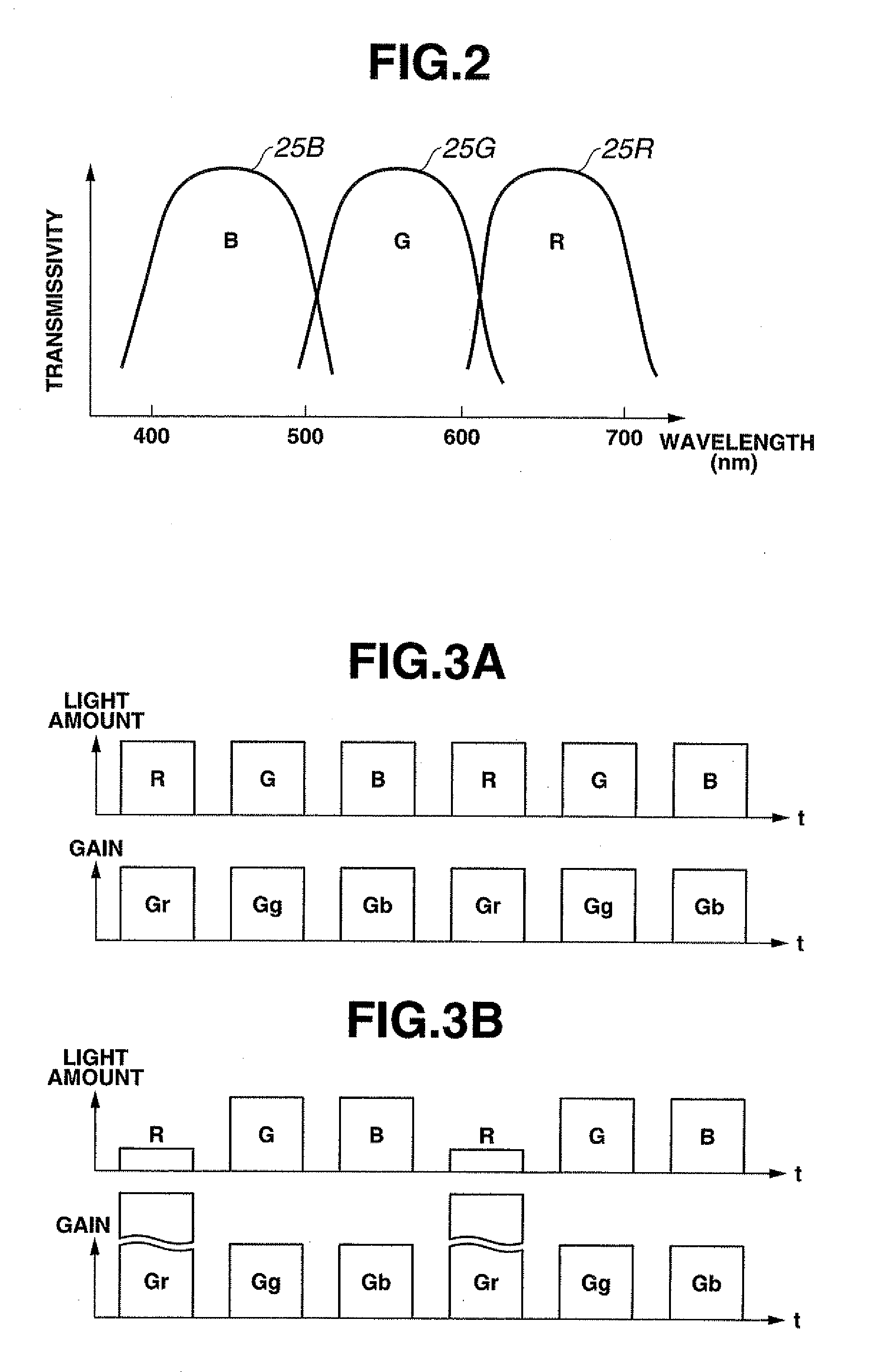
[0032]Referring to FIGS. 1 to 4B, a first embodiment of the present invention is described.
[0033]As shown in FIG. 1, an endoscope apparatus 1 of the first embodiment of the present invention includes: an electronic endoscope (hereinafter abbreviated as scope) 3 which is insertable into a body cavity and picks up an image of an observation target region 2 such as a diseased part in the body cavity to perform an endoscopic observation etc.; a light source apparatus 4 which is detachably connected with the scope 3, for producing illumination light for observation; a processor 5 which is detachably connected with the scope 3, for performing signal processing, etc. on an image picked-up signal; and a monitor 6 which is connected to the processor 5, inputted with a video signal outputted from the processor 5, and displays an image corresponding to this video signal.
[0034]The scope 3 includes an elongate insertion portion 8 which is inserted into the body cavity, an operation portion 9 pro...
second embodiment
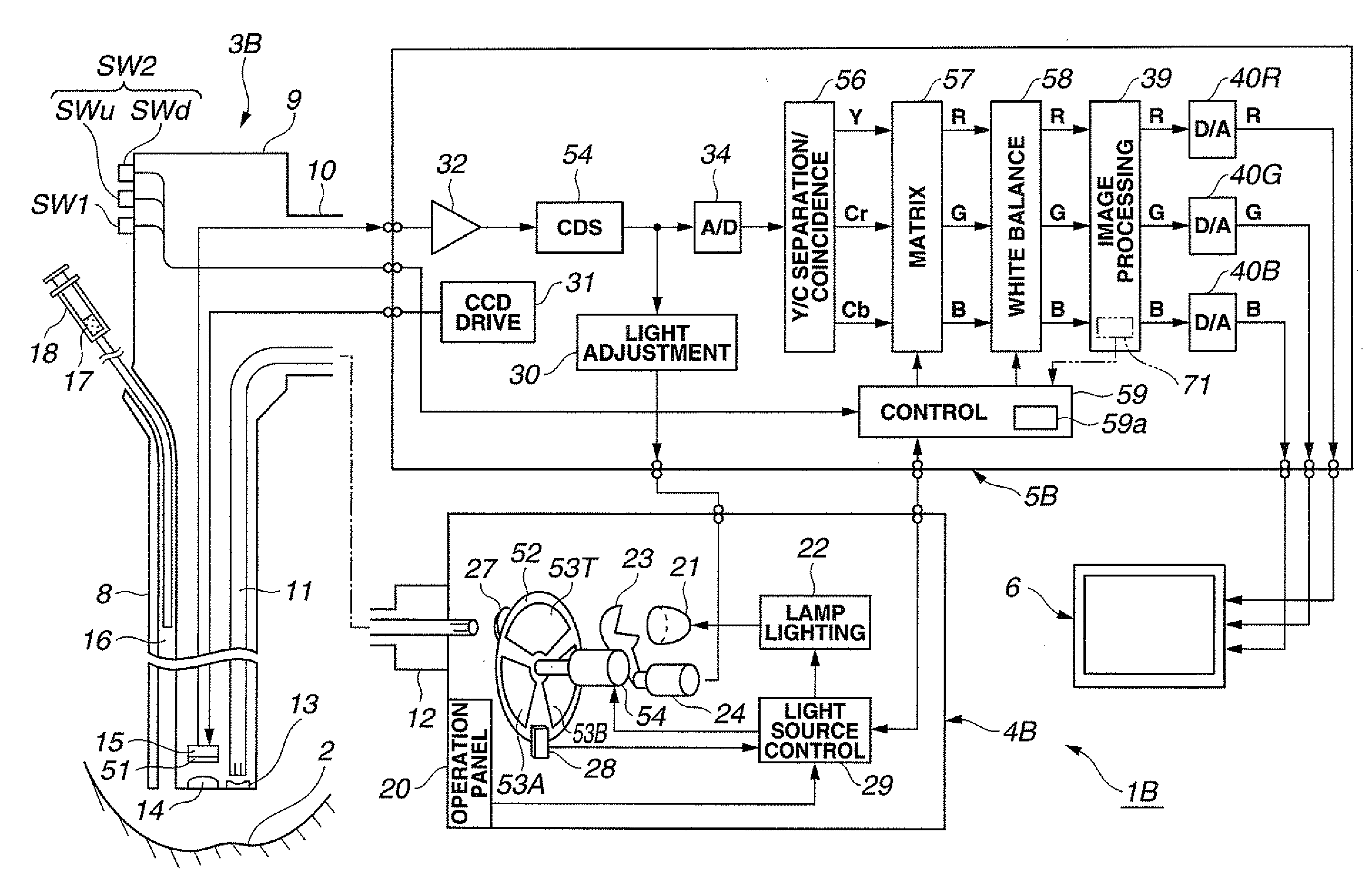
[0093]Next, a second embodiment of the present invention is described referring to FIGS. 5 and 6. FIG. 5 shows a configuration of a coincidence-type endoscope apparatus 1B of the second embodiment.
[0094]The endoscope apparatus 1B includes a scope 3B, a light source apparatus 4B, a processor 5B, and the monitor 6.
[0095]The scope 3B includes a CCD for picking up a color image wherein the image pickup surface of the CCD15 in the scope 3 of FIG. 1 is provided with a color separation filter 51. In other words, the scope 3B is a coincidence-type scope. As in the first embodiment, the operation portion 9 of the scope 3B is provided with the mode change-over switch SW1 for changing over to the first mode which corresponds to the normal observation, the light amount up switch SWu for performing an instruction operation to increase the light amount of the red illumination light in the second observation mode, and the light amount down switch SWd for reducing the light amount. Here, as in the ...
third embodiment
[0119]Next, a third embodiment of the present invention is described referring to FIG. 7. The third embodiment has a configuration where, for example, a part of the second embodiment is modified. FIG. 7 shows a configuration of a light source apparatus 4C in the third embodiment. The light source apparatus 4C is configured such that, in place of the filter plate 52 provided in, e.g., the light source apparatus 4B in FIG. 5, a filter inserting / removing apparatus 61 selectively arranges one of a plurality of filters 62a to 62c in the illumination light path.
[0120]Action of the filter inserting / removing apparatus 61 is controlled by the light source control circuit 29. In the present embodiment, a state where none of the filters are arranged in the illumination light path corresponds to the state in the second embodiment where the transparent portion 53T is arranged in the illumination light path, that is, the normal observation.
[0121]A state where the first filter 62a or the second fi...
PUM
 Abstract
Description
Claims
Application Information
 - R&D
- Intellectual Property
- Life Sciences
- Materials
- Tech Scout
- Unparalleled Data Quality
- Higher Quality Content
- 60% Fewer Hallucinations
Browse by: Latest US Patents, China's latest patents, Technical Efficacy Thesaurus, Application Domain, Technology Topic, Popular Technical Reports.
© 2025 PatSnap. All rights reserved.Legal|Privacy policy|Modern Slavery Act Transparency Statement|Sitemap|About US| Contact US: help@patsnap.com


