Optical fiber

a technology of optical fibers and fibers, applied in the field of optical fibers, can solve the problems of deterioration of optical signals, inability to maintain stable characteristics in the longitudinal direction of optical fibers, and becoming an obstacle to light propagation in optical fibers

Inactive Publication Date: 2009-06-11
FURUKAWA ELECTRIC CO LTD
View PDF3 Cites 19 Cited by
  • Summary
  • Abstract
  • Description
  • Claims
  • Application Information

AI Technical Summary

Benefits of technology

[0008]It is an object of the present invention to at least partially solve the problems in the conventional technology.

Problems solved by technology

When the SBS is generated, it becomes an obstacle to a light propagation in the optical fiber.
However, with the optical fibers described in Japanese Patent No. 2584151, Japanese Patent No. 2753426, and Japanese Patent No. 3580640, in which the characteristics are changed in the longitudinal direction, even though the generation of the SBS can be suppressed owing to an increase of the SBS threshold, there is a problem that the characteristics cannot be maintained stable in the longitudinal direction of the optical fiber.
As a result, when an optical signal propagates through the optical fiber, there is a possibility of degradation of the optical signal, such as distortion of a signal waveform, when the optical signal passes through a portion of the fiber where the characteristics are locally changed.
Although the optical fiber described in Japanese Patent Application Laid-Open No. 2006-133314 does not have a change of the characteristics in the longitudinal direction, the effect of increasing the SBS threshold is not enough.

Method used


Image

  • Optical fiber
  • Optical fiber
  • Optical fiber

Examples


Embodiment Construction

[0032]Exemplary embodiments of an optical fiber according to the present invention will be explained in detail below with reference to the accompanying drawings. However, the present invention is not to be considered limited to the embodiments.

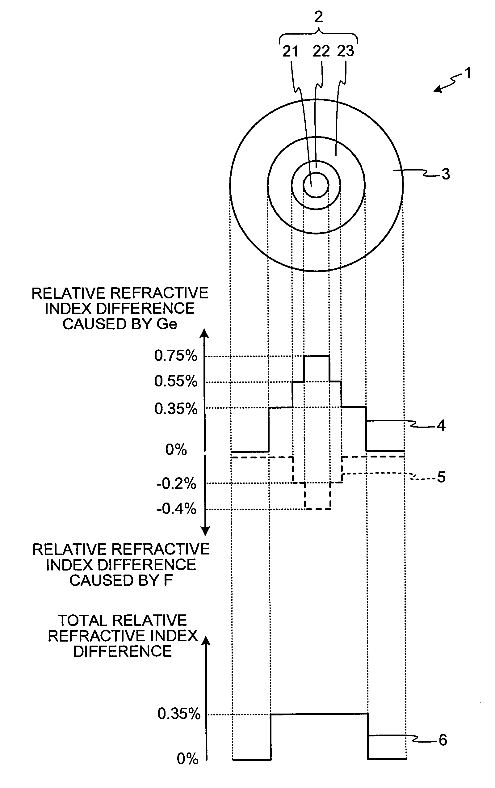
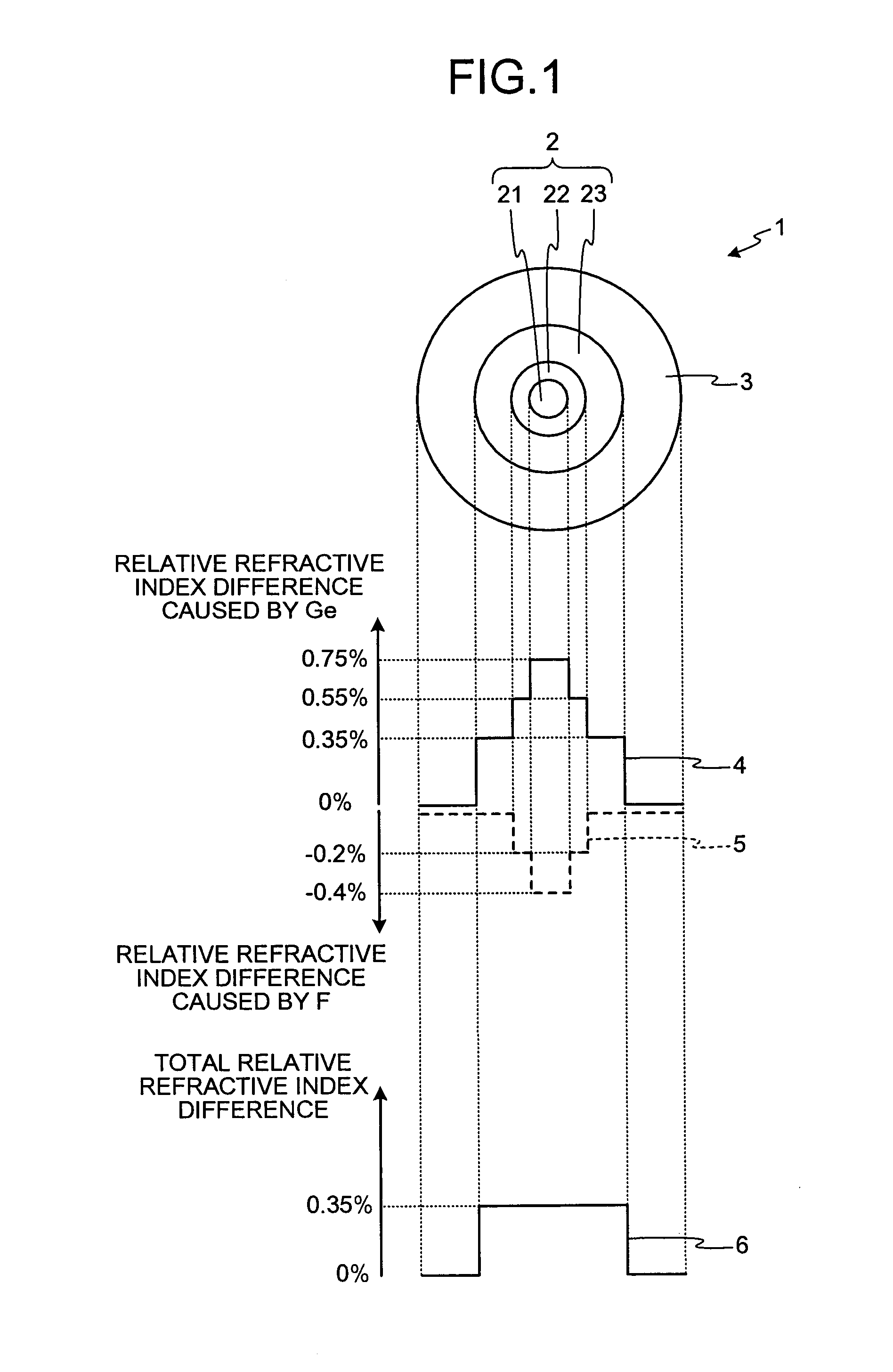
[0033]FIG. 1 is a schematic diagram for illustrating a cross section and a refractive index profile of an optical fiber 1 according to an embodiment of the present invention. As shown in FIG. 1, the optical fiber 1 according to the present embodiment is a single-mode optical fiber including a core 2 and a cladding 3 that is formed on the outer circumference of the core 2.

[0034]The core 2 includes a center core layer 21, an inner core layer 22, and an outer core layer 23, having three concentric outer circumferences including a layer that is doped with at least one of germanium (Ge) and fluorine (F). The Ge is doped as a form of GeO2. The cladding 3 is formed with a pure silica glass that does not contain any dopant for changing the refractive ...


PUM


Abstract

A silica-based optical fiber includes a core and a cladding that is formed on an outer circumference of the core. The core includes three or more layers including a layer doped with at least one of germanium and fluorine, and a concentration of the germanium or the fluorine in each of the layers is controlled in such a manner that a Brillouin gain spectral peak is spread into a plurality of peaks on a Brillouin gain spectrum. With this scheme, an optical fiber is provided, which has stable characteristics in the longitudinal direction, and which has a high SBS threshold so that generation of the SBS can be effectively suppressed.

Description

CROSS-REFERENCE TO RELATED APPLICATIONS[0001]This application is a continuation of PCT international application Ser. No. PCT / JP2007 / 063255 filed Jul. 2, 2007 which designates the United States, incorporated herein by reference, and which claims the benefit of priority from Japanese Patent Application No. 2006-182393, filed Jun. 30, 2006, incorporated herein by reference.BACKGROUND OF THE INVENTION[0002]1. Field of the Invention[0003]The present invention relates to an optical fiber that can suppress generation of stimulated Brillouin scattering.[0004]2. Description of the Related Art[0005]To realize a large-capacity optical communication, a wavelength-division-multiplexing (WDM) system or a time-division-multiplexing (TDM) system has been adopted. In this kind of communication system, when the optical intensity input to an optical fiber, which is a transmission line, increases, generation of a nonlinear optical phenomenon in the optical fiber becomes prominent. The stimulated Brill...

Claims


Application Information

Patent Timeline
Patent Type & Authority Applications(United States)
IPC IPC(8): G02B6/036
CPCG02B6/02019G02B6/03638G02B6/02266
Inventor KOYAMADA, YAHEIIMAMURA, KATSUNORI
Owner FURUKAWA ELECTRIC CO LTD
Why Eureka
Try Eureka