
Geothermal Air Conditioning with Desiccant Dehumidification

Inactive Publication Date: 2009-06-11
SHAPIRO IAN M
View PDF16 Cites 15 Cited by
  • Summary
  • Abstract
  • Description
  • Claims
  • Application Information

AI Technical Summary

Benefits of technology

[0004]Accordingly, it is an object of the invention to provide a geothermal air conditioning system that also dehumidifies the indoor air, and achieves higher efficiency (and reduced cost of cooling and dehumidification) than is achieved in the prior art.
[0007]It is a further object to facilitate enhanced humidity control of the indoor air, and to allow integrated high-efficiency heating by use of the same system.
[0017]Because there is no outdoor heat exchanger coil and no outdoor fan, there is a considerable savings in terms of hardware and in terms of energy for moving the outdoor air through an outdoor coil.

Problems solved by technology

However, in most parts of the U.S., the temperature of geothermal water coming from the geothermal well is not cold enough for dehumidification or latent cooling.
Geothermal cooling can be used for “free” cooling of air, but the water being circulated is not cold enough, by itself, for dehumidification.

Method used


Image

  • Geothermal Air Conditioning with Desiccant Dehumidification
  • Geothermal Air Conditioning with Desiccant Dehumidification
  • Geothermal Air Conditioning with Desiccant Dehumidification

Examples


Embodiment Construction

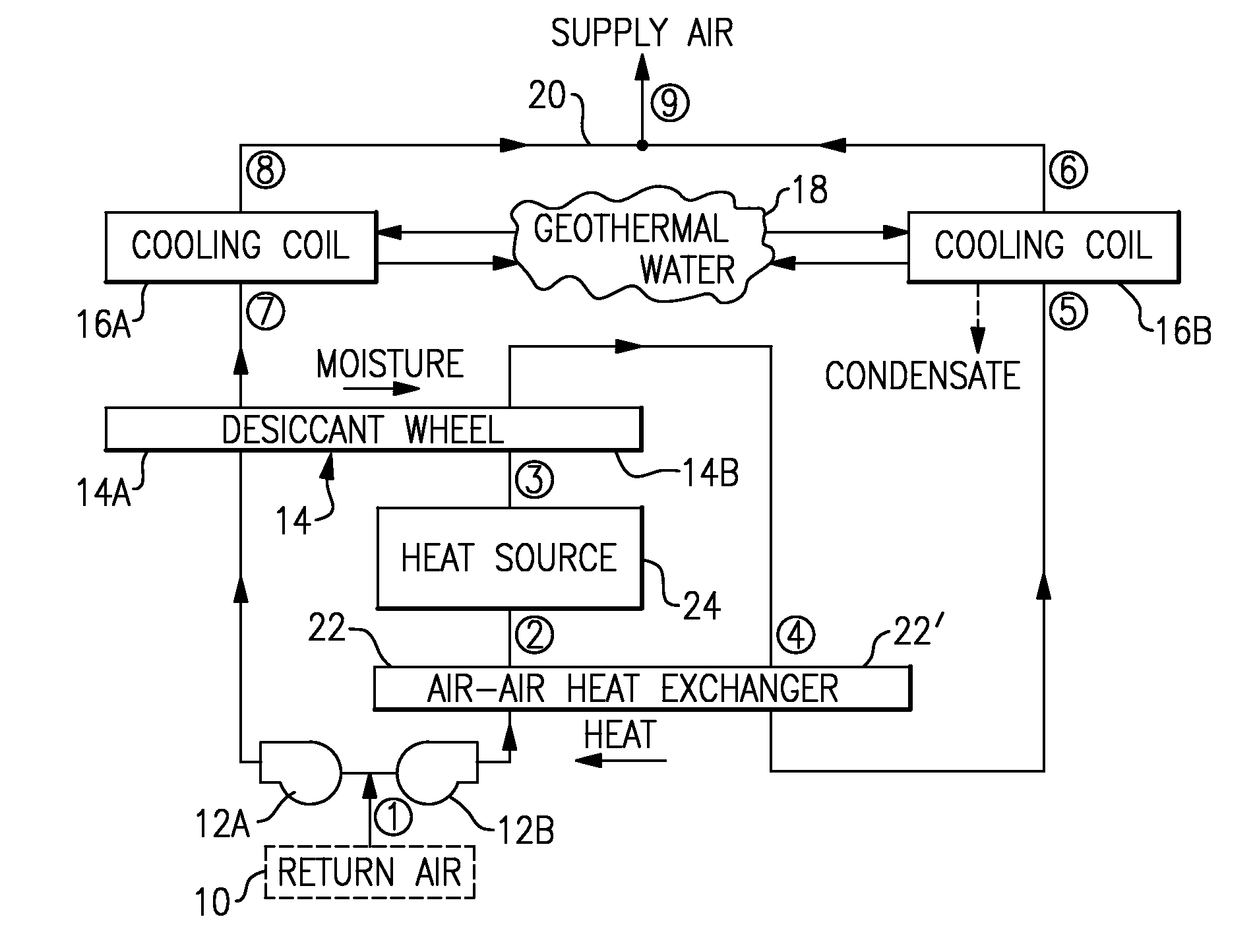
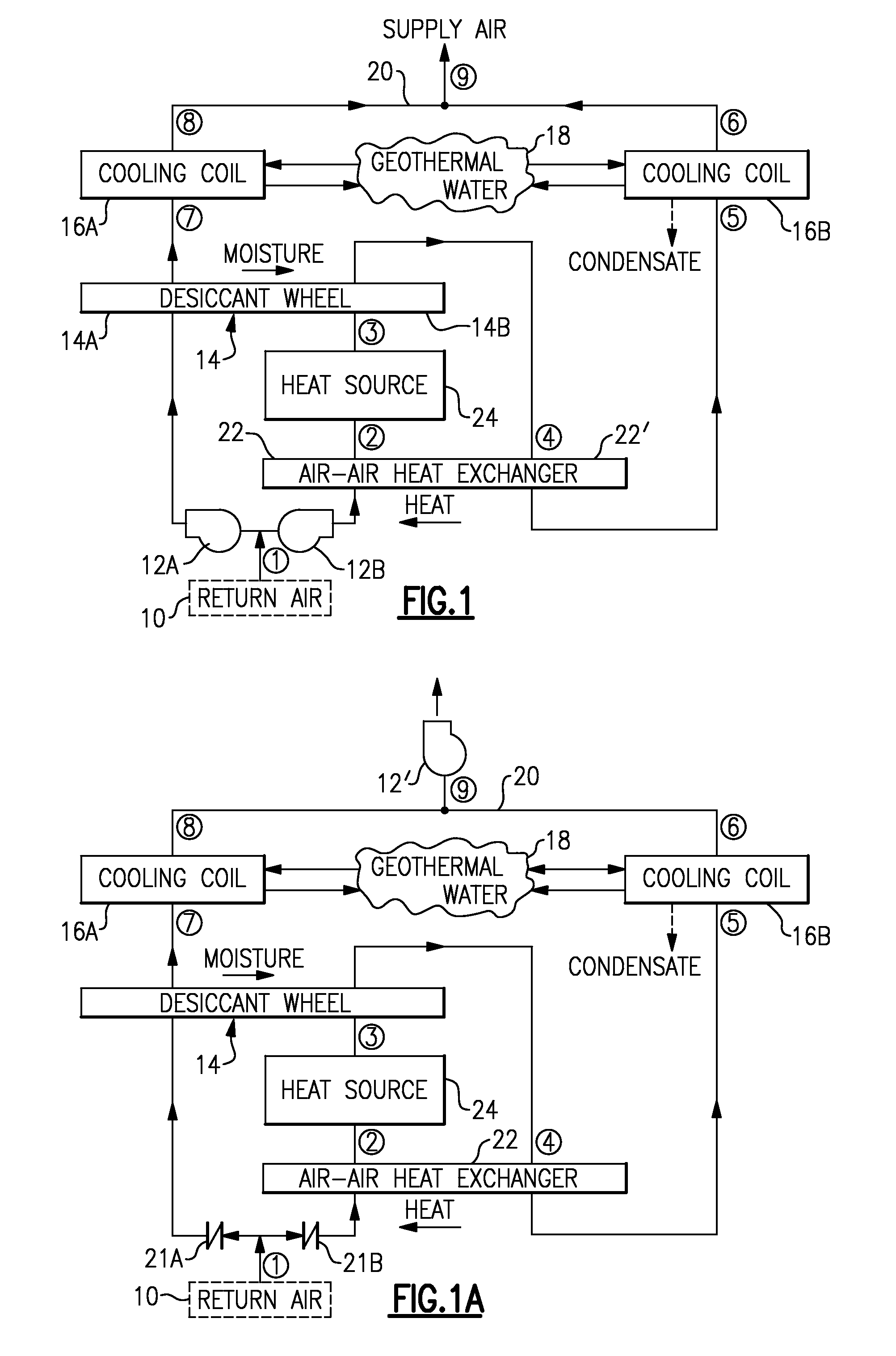
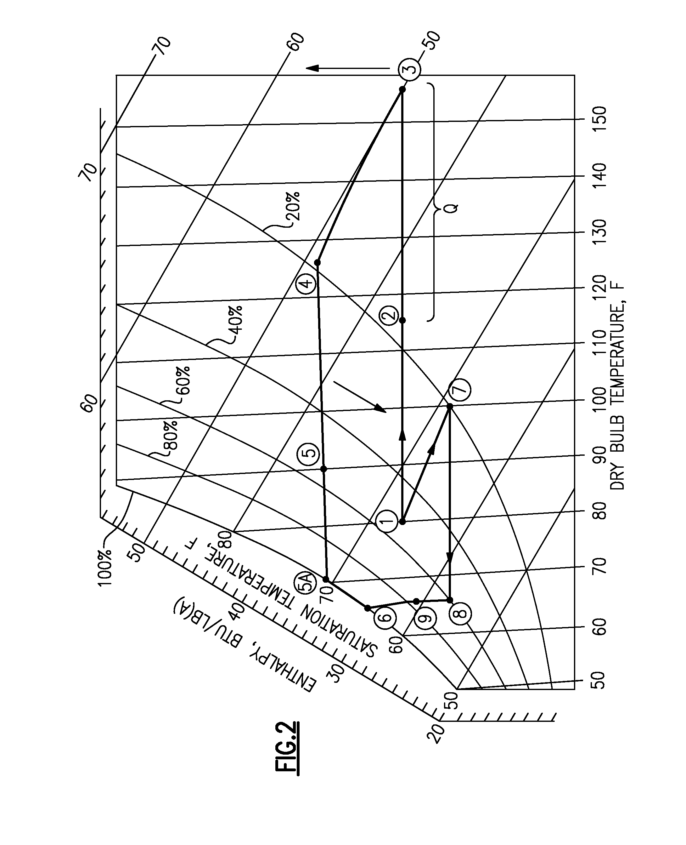
[0025]With reference to the Drawing, a geothermal and desiccant cycle air conditioning and dehumidification arrangement is shown schematically in FIG. 1. At the bottom of the drawing view, a return air duct or inlet 10 receives the warm and moist air from the room or conditioned space. The air is split into first and second air flows or courses, with a pair of blowers or fans 12A and 12B moving the air respectively along the first and second courses. The first air stream or course is shown at the left. This air stream first passes through a desiccant wheel 14, namely, through the dehumidification or drying side 14A thereof, where the desiccant materials in the wheel pick up moisture from this first air stream. The wheel 14 is rotated to convey the moisture to the second air stream where that air is heated and passes through the rotated or wet side 14B to pick up the moisture from the desiccant. This will be discussed later. The dehumidified first course air stream leaving the desicc...


PUM


Abstract

A geothermal desiccant cycle cools and dehumidifies the air in an indoor conditioned space. The return air is split into two streams. One of the streams passes through a desiccant wheel to remove water vapor and then through a cooling coil for sensible cooling from geothermal water. The other stream is heated to increase its capacity to absorb moisture, and then is passed through the desiccant wheel to pick up the moisture transferred from the first stream and regenerate the desiccant. The second air stream, which now has a higher dewpoint temperature, flows through a geothermal cooling coil, for sensible cooling as well as condensation of the moisture. The two air streams are mixed and supplied back to the conditioned space. A regenerative air-air heat exchanger can be used to recover some of the heat used in heating the second air stream.

Description

BACKGROUND OF THE INVENTION[0001]This invention relates to geothermal heating and cooling, and is more particularly concerned with a closed system in which geothermal water is used for removing sensible heat from indoor air, and a desiccant wheel is employed for removing humidity. The invention is more specifically directed to a geothermal air conditioning system in which the air stream is split into first and second air streams or courses, for removing both heat and humidity.[0002]Abundant cooling resources are available from the earth in the form of geothermal cooling, which does not require significant energy to obtain, and which does not result in discharge of waste heat into the atmosphere. Geothermal cooling can be obtained by circulating water (or another heat exchange medium) through pipes that run to and from one or more geothermal wells. Because the ground temperature is constantly cooler than the temperature required for indoor air, geothermal sensible cooling appears to ...

Claims


Application Information

Patent Timeline
IPC IPC(8): F25D17/06
CPCF24F3/1423F24F5/0046Y02B30/563Y02B10/40F24F12/006Y02B30/56
Inventor SHAPIRO, IAN M.
Owner SHAPIRO IAN M
Learn More