
Display apparatus, liquid crystal display apparatus, position detection system and position detection method

Inactive Publication Date: 2009-06-04
PIONEER CORP
View PDF3 Cites 26 Cited by
  • Summary
  • Abstract
  • Description
  • Claims
  • Application Information

AI Technical Summary

Benefits of technology

[0005]Moreover, in the analog capacitance coupling method, a conductive thin film is provided on the screen of the display apparatus. Thus, the visibility on the screen may decrease in some cases.
[0006]On the other hand, the infrared method does not require anything on the screen of the display apparatus. Thus, the visibility is excellent. In this method, however, an infrared light emitting diode and a photo transistor are provided in a frame portion of the screen. Thus, the frame portion requires a space to be provided with those members, which makes it difficult to thin the frame portion and reduces the width of the frame portion.
[0008]In view of the above-exemplified problems, it is therefore a first object of the present invention to provide a display apparatus, a liquid crystal display apparatus, a position detection system and a position detection method, which can realize the simplification of the hardware structure of the display apparatus, a reduction in costs, a reduction in a size, or a reduction in restrictions on the setting and design, while realizing the position detection in the display screen.
[0010]It is a third object of the present invention to provide a display apparatus, a liquid crystal display apparatus, a position detection system and a position detection method, which allow the position detection in the display screen without reducing the visibility of the display screen.
[0011]It is a fourth object of the present invention to provide a display apparatus, a liquid crystal display apparatus, a position detection system and a position detection method, which allow the position detection in the display screen without reducing the durability.Means for Solving the Subject

Problems solved by technology

Thus, visibility on the screen may decrease in some cases.
Moreover, in the resistive film method, the film is pressed down to detect the contact, which easily damages the film.
Thus, it is hard to increase the durability of the display apparatus equipped with the touch panel.
Thus, the visibility on the screen may decrease in some cases.

Method used


Image

  • Display apparatus, liquid crystal display apparatus, position detection system and position detection method
  • Display apparatus, liquid crystal display apparatus, position detection system and position detection method
  • Display apparatus, liquid crystal display apparatus, position detection system and position detection method

Examples


Embodiment Construction

[0060]Hereinafter, the best mode for carrying out the invention will be explained in each embodiment in order, with reference to the drawings.

[0061](Outline of Position Detection System)

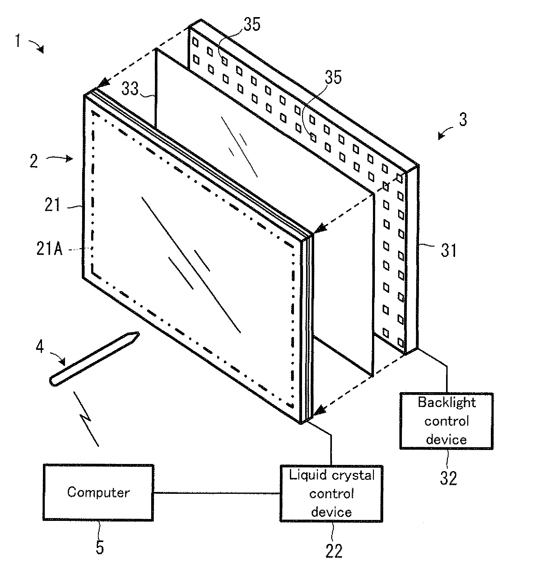
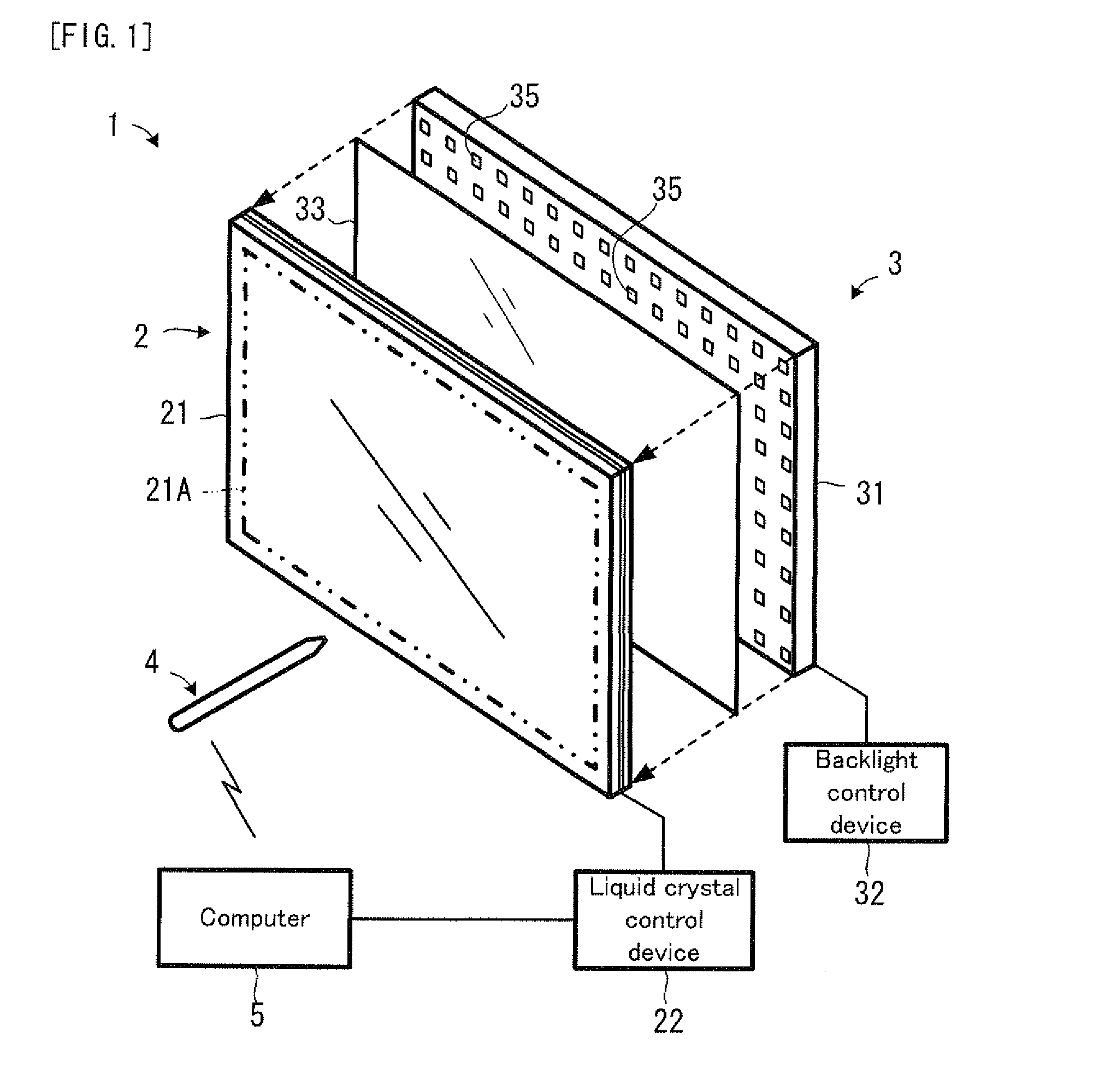
[0062]FIG. 1 shows the case that the position detection system of the present invention is applied to a liquid crystal display apparatus. A position detection system 1 in FIG. 1 can detect a position in a display surface 21A of a liquid crystal panel apparatus 2. The display surface 21A is a surface to perform thereon the visual display of information, such as a character and a figure. The position detection system 1 is provided with: a backlight apparatus 3; and a light receiving apparatus 4. Incidentally, a combination of the liquid crystal panel apparatus 2 and the backlight apparatus 3 is a specific example of the display apparatus. Moreover, the backlight apparatus 3 is a specific example of the light emitting apparatus.

[0063]The backlight apparatus 3 has a function as a backlight for emitting l...


PUM


Abstract

Backlight of a backlight device (3) attached to a liquid crystal panel device (2) is created by a multitude of light emitting diodes, and light emitted from each light emitting diode is modulated by position information indicating the position of a display screen (21A). The light receiving device (4) receives the backlight, modulates it, takes out the position information and detects the position on a display screen (21A) based on the position information.

Description

TECHNICAL FIELD[0001]The present invention relates to a display apparatus, such as a liquid crystal display apparatus, a plasma display apparatus, and an organic EL (Electro-luminescence) display apparatus, and more specifically relates to a position detection system for and a position detection method of detecting a position in a display surface on such a display apparatus, and further relates to a display apparatus provided with such a position detection function.BACKGROUND ART[0002]As an apparatus which can detect a position in a screen (display surface) of a display apparatus, a touch panel is known. According to the touch panel, when a user touches the screen with a finger, a pen, a stylus or the like, this contact position is detected, and coordinate information or the like, which indicates the contact position, is sent to a computer or the like. This type of touch panel is used for a PDA (Personal Digital Assistance), a high-functional mobile phone, a car navigation apparatus...

Claims


Application Information

Patent Timeline
IPC IPC(8): G06F3/042G09F13/08G02F1/13357G09G3/36
CPCG02F1/13338G02F1/133603G09G2320/0247G06F3/03545G09G3/3406G06F3/03542
Inventor KURODA, KAZUOIMAMURA, AKIRATANAKA, KEI
Owner PIONEER CORP
Learn More