
Ergonomically designed dispenser for stretch film

a dispenser and ergonomic design technology, applied in the direction of thin material handling, packaging, filament handling, etc., can solve the problems of difficult to push the dispenser into the core, the dispenser cannot adjust to the variations of the inside dimensions of the film core, and the film roll cannot be rolled. achieve the effect of good balance and facilitate the application of film

Inactive Publication Date: 2009-05-21
M S PLASTICS
View PDF9 Cites 17 Cited by
  • Summary
  • Abstract
  • Description
  • Claims
  • Application Information

AI Technical Summary

Benefits of technology

[0019]A common problem that has occurred with prior art dispensing devices is that they do not adjust to the variations of the inside dimensions of the film core. If the film core is too large, the roll of film will slip out of the dispenser. Conversely, if the core is too tight, it is very difficult to push the dispenser into the core and equally as difficult to remove the dispenser when the film is used up. By using the device of the present invention, by merely pressing the front end of the split barrel, it allows the film roll to slip on or off the barrel. When in use, the barrel springs back and the raised lip prevents the film from slipping off the barrel.
[0020]It is an object of the present invention for the barrel or shaft of the device to be split which allows it to be compressed and easily inserted into the film core. It is an object of the present invention for the front end of the barrel to have a raised lip. After the barrel is inserted into the film core, the raised lip that extends beyond the end of the core prevents the dispenser from coming out.
[0021]The present invention comprises a 1″ ID core for dispensing film. This improves the dispensing of film which is commonly done with standard 3″ ID core dispensers. The use of a 1″ ID core substantially reduces the OD of the film roll, making it easier and less cumbersome to use. It is an object of the present invention to use the device with approximately 1″ to 6″ width films.
[0022]It is an object of the present invention for dispenser to comprise a knob at the base of the handle to comprise a tapered screw. When turned clockwise, it extends between two cams located opposite each other on the interior of the barrel which expands the barrel against the inside of the core on which the stretch wrap is wound and provides adjustable and constant tension.
[0027]It is an object of the present invention to provide a stretch wrap dispenser which has good balance and facilitates the application of film under substantially uniform tension across the full width of the film for a uniform wrap.
[0028]It is an object of the present invention to provide a stretch wrap film dispenser which can be adjusted to accommodate different widths of film rolls.

Problems solved by technology

A common problem that has occurred with prior art dispensing devices is that they do not adjust to the variations of the inside dimensions of the film core.
If the film core is too large, the roll of film will slip out of the dispenser.
Conversely, if the core is too tight, it is very difficult to push the dispenser into the core and equally as difficult to remove the dispenser when the film is used up.

Method used


Image

  • Ergonomically designed dispenser for stretch film
  • Ergonomically designed dispenser for stretch film

Examples


Embodiment Construction

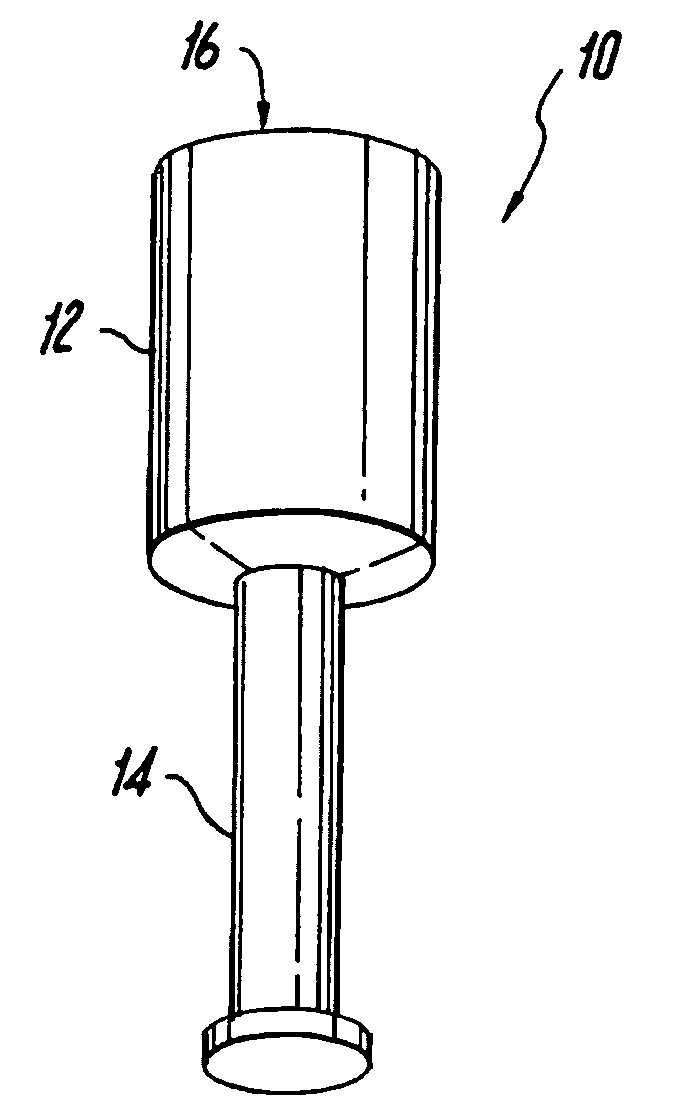
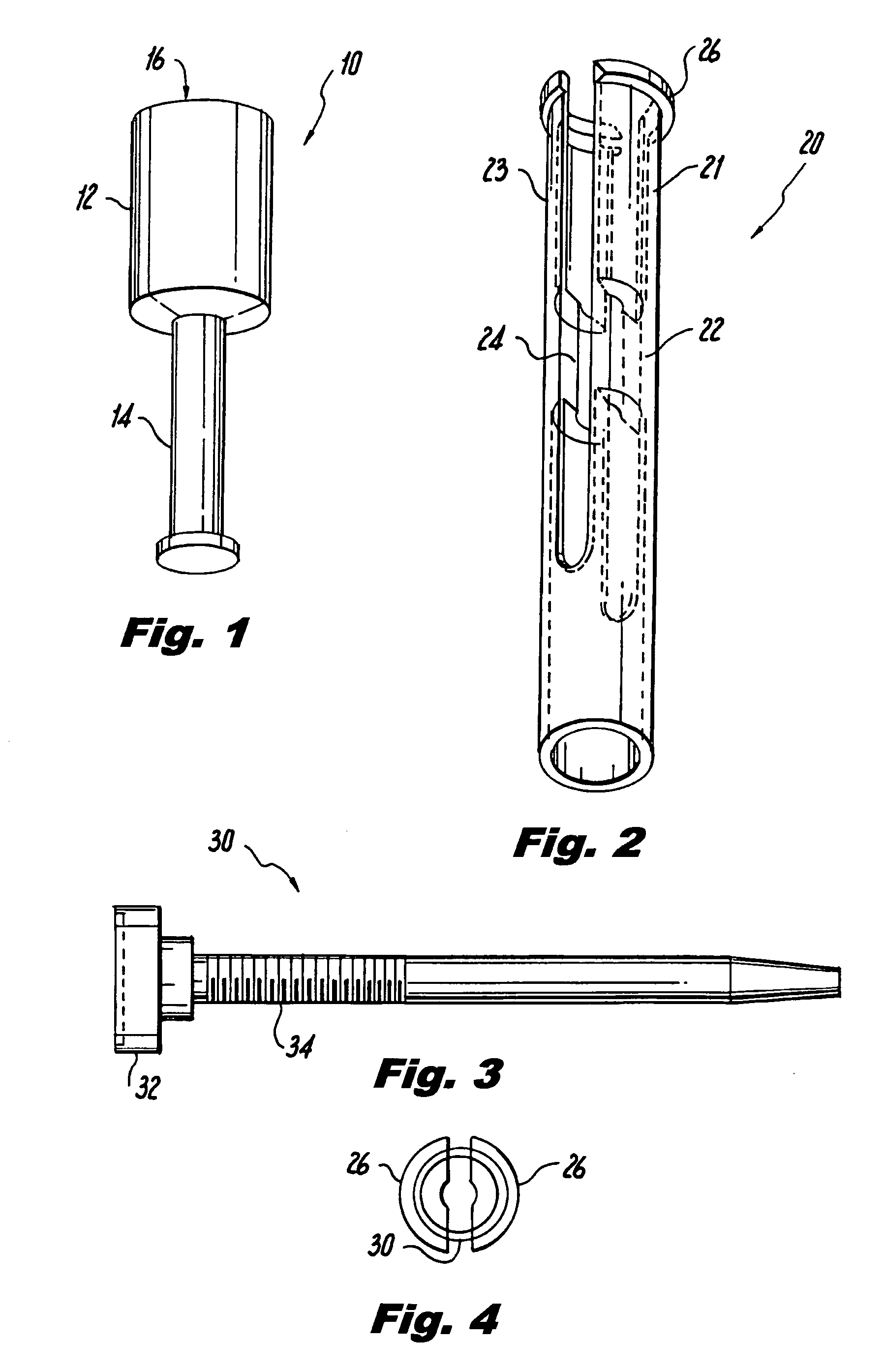
[0034]FIG. 1 shows a dispenser 10 for dispensing stretch film 12 having a handle 14. The handle 14 in a preferred embodiment being molded. In a preferred embodiment, the dispenser 10 has a foam sleeve for a cushion grip which fits over the handle 14.

[0035]FIG. 2 shows the barrel or shaft 20 of the dispenser 10. The barrel or shaft 20 of the dispenser 10 is split into two pieces 21 and 23 which allows the barrel 20 to be compressed and easily inserted into the film core 16. The barrel has located internally two cams 22 and 24. In a preferred embodiment, the front end of the barrel 20 has a raised lip 26. After the barrel 20 is inserted into the film core 16, the raised lip 26 extends beyond the end of the core 16 and prevents the stretch film 12 from coming out of the dispenser 10.

[0036]FIG. 3 shows the tensioning device 30 of the dispenser 10 of the present invention. The tensioning device 30 comprises a knob 32 at the base of the tensioning device 30 and a tapered screw 34. The ten...


PUM


Abstract

A hand dispenser for stretch film. The stretch film from the hand dispenser is dispensed by using one hand from a person. The film is wound around one end of the extended core. The dispenser comprises a handle; a split barrel or shaft and a tensioning device inserted in the barrel for creating tension against a core of stretch film.

Description

FIELD OF THE INVENTION[0001]The present invention relates to an ergonomically designed dispenser for use with stretch film.BACKGROUND OF THE INVENTION[0002]U.S. Pat. No. 4,722,493 relates to a holder for dispensing stretch film from a roll comprising a cylindrical body and an arbor rotatably supported on the body. A flexible grip having internal ribs covers the body and the arbor, so that one can by applying finger pressure to the grip brake rotation of the arbor and thus control film tension. The patent teaches that the holder comprises a handle which includes a substantially cylindrical body and a shaft extending from one end of the body. An arbor is journaled on the shaft. Means on the arbor engage the film roll, thereby constraining the roll and the arbor to rotate together on the shaft. A collar is on the arbor adjacent the handle body. One holding the handle body may create a braking torque on the roll by applying radial pressure to the collar.[0003]U.S. Pat. No. 5,203,517 rel...

Claims


Application Information

Patent Timeline
Patent Type & Authority Applications(United States)
IPC IPC(8): B65H23/06
CPCB65B67/085
Inventor SARAISKY, AL
Owner M S PLASTICS
Learn More