
Method and apparatus for generation of datamatrix barcodes utilizing numerical control drilling patterns

a numerical control and barcode technology, applied in the field of datamatrix barcodes, can solve the problems of increasing surface friction, label attachment to the wrong part or inadvertently removed or lost, and the inability to use line-type barcodes on some very small parts

Inactive Publication Date: 2009-05-14
THE BOEING CO
View PDF16 Cites 16 Cited by
  • Summary
  • Abstract
  • Description
  • Claims
  • Application Information

AI Technical Summary

Problems solved by technology

In fact, line-type barcodes cannot be used on some very small parts due to the space requirements of the line-type barcodes.
However, these labels can be attached to the wrong part or inadvertently removed or lost.
This raised surface can cause interference between close tolerance mating parts and increase surface friction.
Thus, laser marking may be frequently limited to utilization on small parts which can be housed in an enclosure.
Resulting heat damage to sensitive parts may cause stress cracking and is therefore, not approved, for use in many areas and for use on some parts.
Thus, traditional methods of subsurface marking may be characterized by expensive standalone equipment, separate part setups, trial and error results on unique parts, and material displacement on flat surfaces.
Users are required to invest in separate equipment, some of which cannot be used on critical parts.
In addition, a time delay may be present between the time that a part has completed the manufacture process and the point at which the part is placed on the specialized equipment for marking with a datamatrix barcode.

Method used


Image

  • Method and apparatus for generation of datamatrix barcodes utilizing numerical control drilling patterns
  • Method and apparatus for generation of datamatrix barcodes utilizing numerical control drilling patterns
  • Method and apparatus for generation of datamatrix barcodes utilizing numerical control drilling patterns

Examples


Embodiment Construction

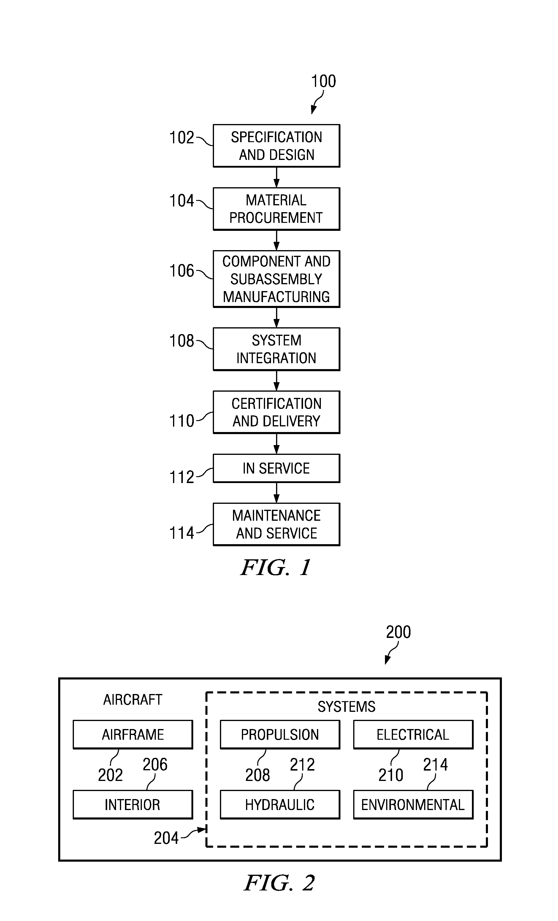
[0026]Referring more particularly to the drawings, embodiments of the disclosure may be described in the context of the aircraft manufacturing and service method 100 as shown in FIG. 1 and aircraft 200 as shown in FIG. 2. Turning first to FIG. 1, a diagram illustrating an aircraft manufacturing and service method is depicted in accordance with an advantageous embodiment. During pre-production, exemplary aircraft manufacturing and service method 100 may include specification and design 102 of aircraft 200 in FIG. 2 and material procurement 104.

[0027]During production, component and subassembly manufacturing 106 and system integration 108 of aircraft 200 in FIG. 2 takes place. After manufacture, parts of aircraft 200 in FIG. 2 are labeled with datamatrix barcodes. Datamatrix barcodes are used on parts to produce machine readable identification utilizing a small area of the part.

[0028]Thereafter, aircraft 200 in FIG. 2 may go through certification and delivery 110 in order to be placed...


PUM

PropertyMeasurementUnit
sizeaaaaaaaaaa
sizeaaaaaaaaaa
grid sizeaaaaaaaaaa

Abstract

The illustrative embodiments provide a method, apparatus, and computer usable program product for generating datamatrix barcodes on parts. A digital datamatrix code associated with a machined part on a numerically controlled machine tool is converted into an x-y drilling pattern contained in a numerically controlled program. A drill cycle associated with a numerically controlled program defines a pattern of dots to be drilled in the machined part to form a dot pattern. A dot pattern is drilled as a series of partially drilled holes on a surface of the machined part to form a datamatrix barcode mark.

Description

BACKGROUND INFORMATION[0001]1. Field:[0002]The present disclosure relates generally to datamatrix barcodes and in particular to a method and apparatus for generating datamatrix barcodes. More particularly, the disclosure is directed to a method, apparatus, and computer usable program code for utilizing numerically controlled milling machines to generate datamatrix barcodes on parts.[0003]2. Background:[0004]A barcode is a machine-readable representation of information. Datamatrix barcodes may be two-dimensional matrix barcodes consisting of dots arranged in a square or rectangular pattern. The pattern of the dots may encode information such as, without limitation, part numbers, manufacturer identifier, part description, unique serial numbers, and / or any other suitable details describing the part. Datamatrix barcodes are typically used to encode data on small parts because datamatrix barcodes can encode more information in a smaller area than more traditional barcodes that use parall...

Claims


Application Information

Patent Timeline
Patent Type & Authority Applications(United States)
IPC IPC(8): G06F19/00G06K19/06
CPCG06K1/05G06K1/12G06K19/063Y10T409/500164Y10T408/08Y10T409/300168Y10T409/100159
Inventor BAJOCICH, ALBERT M.BAER, DAVID J.HALL, KENT A.
Owner THE BOEING CO
Learn More