Eureka AIR delivers breakthrough ideas for toughest innovation challenges, trusted by R&D personnel around the world.

Probe for nmr measurement

a nuclear magnetic resonance and probe technology, applied in the direction of magnetic measurement, instruments, measurement devices, etc., can solve the problems of increasing reducing resistance of rf coils, increasing resistances of inductive losses, etc., to achieve high transmitting/receiving efficiency, low resistive loss, and high transmitting/receiving efficiency

Inactive Publication Date: 2009-05-14
HITACHI LTD
View PDF7 Cites 14 Cited by
  • Summary
  • Abstract
  • Description
  • Claims
  • Application Information

AI Technical Summary

Benefits of technology

[0008]It is an object of the present invention to provide an NMR probe that achieves high detection efficiency without decreasing the Q value. In particular, it is an object of the present invention to provide a probe for nuclear magnetic resonance (NMR) measurement that is an NMR probe comprising a multiple resonant circuit for detecting signals of two or more nuclides and that has high detection efficiency for a nuclide at a low resonant frequency.
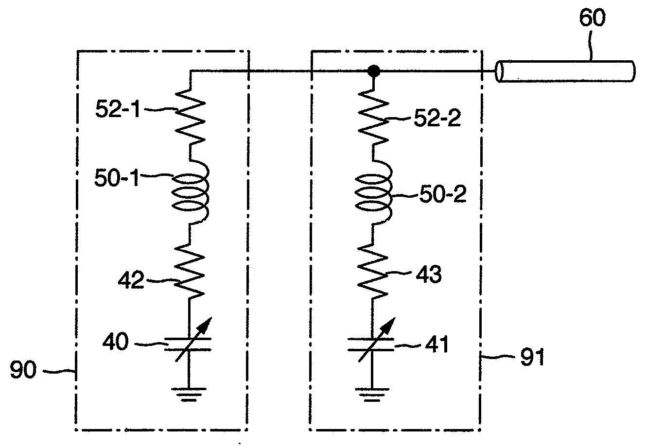
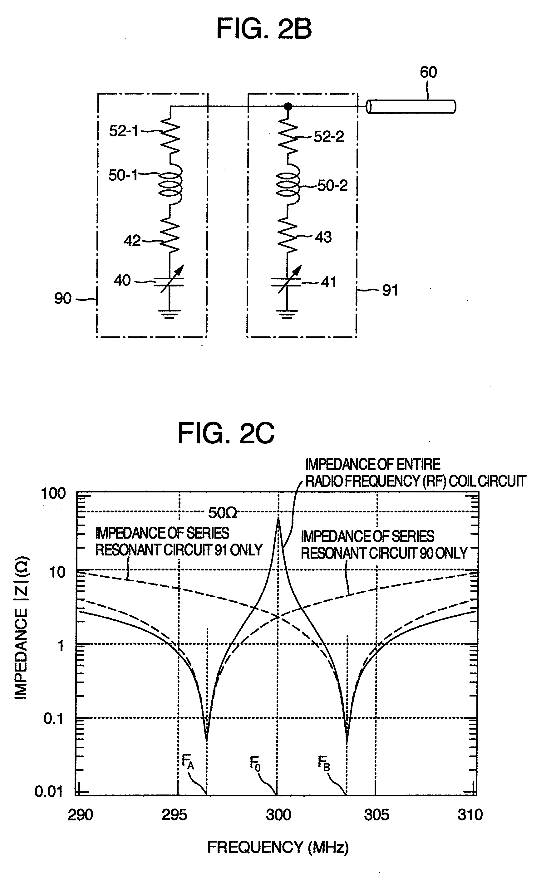
[0009]With multiple lead lines connected to the RF coil, a multiple radio frequency (RF) coil circuit is configured by causing a part of the RF coil, separated by the connection points of lead lines, to function as the inductor of a trap circuit that cuts off a signal at the frequency F1 for a signal at the resonant frequency F1 of a first nuclide and, at the same time, to function as an RF coil that detects a signal at the frequency F2 for a signal at the resonant frequency F2 of a second nuclide, thus increasing the signal detection efficiency for the nuclide at the frequency F2.
[0017]According to the principle of measurement, the signal detection sensitivity of NMR measurement depends on the resonant frequency of a nuclide. The measurement sensitivity of a nuclide having a low resonant frequency is potentially lower than that of a nuclide having a higher resonant frequency. When a double resonant circuit is built, circuit elements are further added to a single resonant circuit. Because the resistive loss of the added elements increases the loss of the entire radio frequency (RF) coil circuit (decreases the Q value), the measurement sensitivity of a nuclide having a low resonant frequency is further decreased.
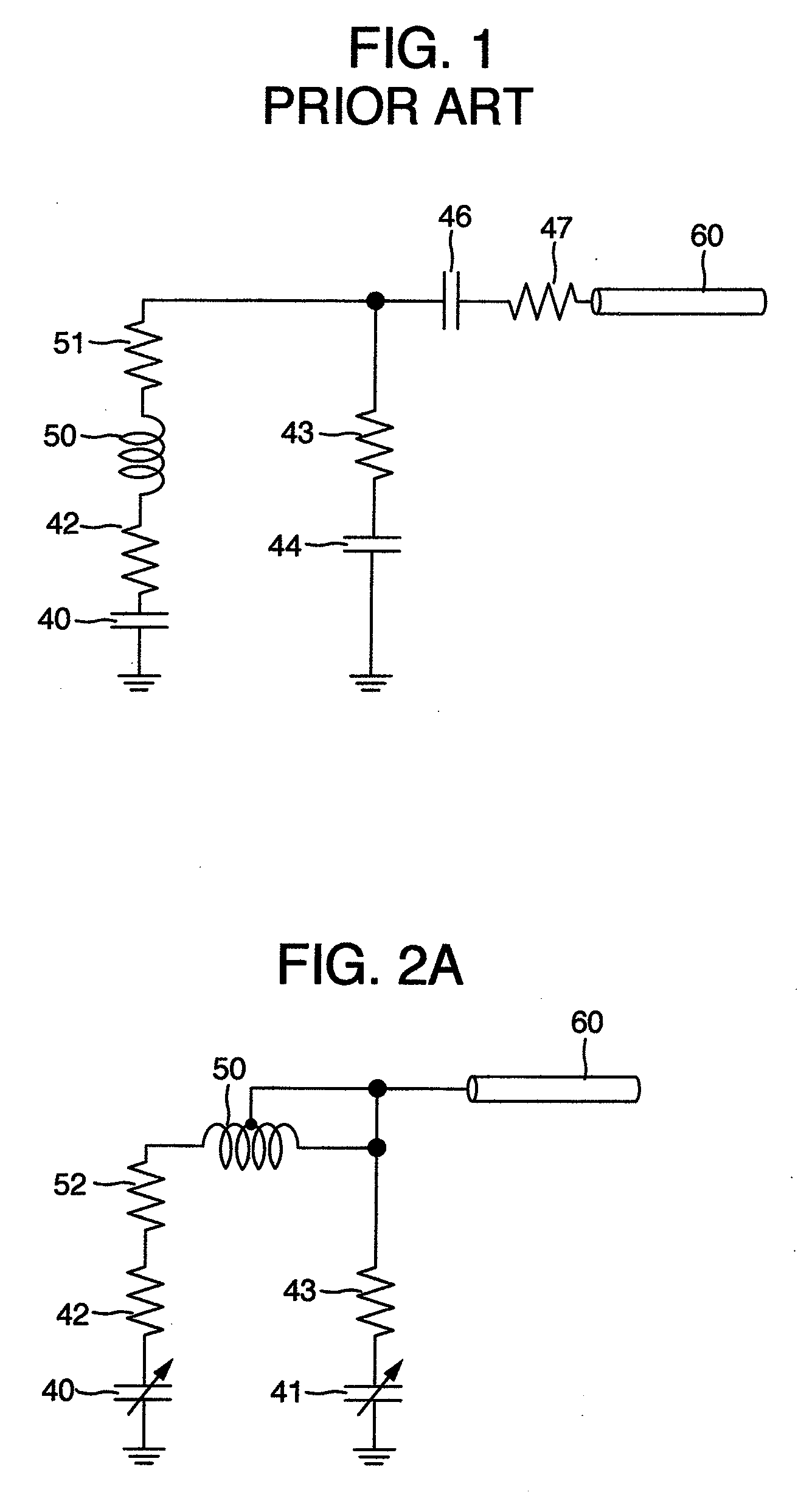
[0024]In the radio frequency (RF) coil circuit of the present invention, the inductance elements required to implement double resonance are used as the RF coil element 1 (L1) and the RF coil element 3 (L3). That is, the present invention is characterized in that the inductor of the trap circuit, which is used only as a component element of an electric circuit in the circuit shown in FIG. 3, is used to detect the signal at the frequency F2 for increasing the signal detection efficiency at the frequency F2. Although the configuration for increasing the signal detection efficiency of a nuclide at a low frequency is disclosed in Patent Document 2 from the same view point, the disclosed configuration is significantly different from the present invention in the circuit configuration.
[0026]As a result, for use in a multiple resonant radio frequency (RF) coil circuit used for a multiple nuclei measuring NMR probe, it is possible to provide the circuit configuration and the implementation method that implement the tuning / matching of resonance characteristics at multiple frequencies without decreasing the Q value of the RF coil, which is normally high, and that ensure high for transmitting / receiving efficiency for a nuclide having a low resonant frequency.
[0027]In particular, because an inductor element used in the multiple resonant circuit configuration may also be used as an RF coil, the efficiency of for transmitting / receiving a high-frequency signal can be increased for a nuclide having a low resonant frequency. In addition, even for a probe using an RF coil that has an extremely low resistive loss such as an RF coil made of normal conduction metal or superconductor cooled down to an extremely low temperature, it is possible to implement a multiple resonance radio frequency (RF) coil circuit that does not decrease the Q value of the RF coil that is normally high.

Problems solved by technology

In this circuit configuration, the capacitance of matching capacitors 44 and 46 is high with the problem that the resistive loss in the circuit is increased.
The problem with a chip capacitor normally used in a radio frequency (RF) coil circuit is that, when the capacitance is increased, the resistances 43 and 47 due to an inductive loss are increased because of the characteristics of the parts.
This problem becomes obvious when the resistance of the RF coil is decreased.
So, even if the RF coil has a high Q value (low resistive loss), the problem is that the Q value of the whole circuit cannot be sufficiently increased because the loss of the capacitor cannot be decreased.

Method used


Image

  • Probe for nmr measurement
  • Probe for nmr measurement
  • Probe for nmr measurement

Examples


first embodiment

[0060]FIG. 6A is a perspective view showing the overview and the arrangement of the main components of an NMR apparatus of the present invention. An evenly distributed magnetic field (static magnetic field) is generated by superconducting magnets 10-1 and 10-2, which are divided into two, along the center line indicated by a chain line. This is indicated by the arrow B0. A sample tube 30, which contains a sample 31, is inserted from the direction vertical to the static magnetic field (x-axis direction in the figure). A probe 20, which contains a solenoidal radio frequency (RF) coil 25 for detecting signals from the sample 31, is inserted from the same direction as that of the static magnetic field. The probe 20 comprises the radio frequency (RF) coil 25 and a probe container 23 in which the radio frequency (RF) coil 25 is stored. Measuring equipment 35 sends a high frequency signal to the radio frequency (RF) coil 25 via the signal line 60, receives a high frequency signal from the ...

second embodiment

[0066]In a second embodiment, a multiple nuclei measuring probe having a solenoidal radio frequency (RF) coil is proposed as in the first embodiment. FIG. 9 is a diagram showing the configuration of a radio frequency (RF) coil in the second embodiment. In this embodiment, a 9-turn solenoidal radio frequency (RF) coil is used. The material of the RF coil is Cu wires. A fifth lead line 75 is connected to the position at which the RF coil element L2 between the point B and the point C in an RF coil 50 is divided into two turns and three turns, and the end of the fifth lead line 75 is connected to the core line of a signal line 60. The other configuration, such as the configuration of lead lines and the arrangement of the trimmer capacitors, are the same as those in the first embodiment.

[0067]As a result of resonance characteristics evaluation made by using the circuit configuration described above as an radio frequency (RF) coil circuit for measuring the H nuclei and the D nuclei, it i...

third embodiment

[0069]In a third embodiment, the configuration, in which a saddle-type probe RF coil is used, is proposed. The saddle-type probe RF coil may be used for an NMR apparatus that generates a vertical direction static magnetic field (B0) using a cylindrical magnet. FIG. 10A is a diagram showing the configuration of the NMR apparatus that generates a vertical direction static magnetic field. A cylindrical superconducting magnet 10 generates an evenly distributed magnetic field along the centerline indicated by a chain line. A probe 20 and a sample tube 30, which contains a sample 31, are inserted from the same direction as that of the static magnetic field (z-axis direction in the figure). The probe 20 comprises a radio frequency (RF) coil 25, a probe end stage 26, and a probe container 23 that contains them. Measuring equipment 35 sends a high frequency signal to the radio frequency (RF) coil 25 via a signal line 60, receives a high frequency signal from the sample 31, analyzes the resul...


PUM


Abstract

A probe for nuclear magnetic resonance (NMR) measurement provided with a multiple resonant circuit for detecting signals of two or more nuclides with high detection efficiency for nuclide at low resonant frequency comprises a multiple resonance radio frequency (RF) coil circuit that, with multiple lead lines connected to the RF coil, causes a part of the RF coil, separated by the connection points of the lead lines, to function as the inductor of a trap circuit that cuts off a signal at the frequency F1 for a signal at the resonant frequency F1 of a first nuclide and, at the same time, to function as an RF coil that detects a signal at the frequency F2 for a signal at the resonant frequency F2 of a second nuclide, thus increasing the signal detection efficiency for the nuclide at the frequency F2.

Description

BACKGROUND OF THE INVENTION[0001]The present invention relates to a probe for a nuclear magnetic resonance apparatus (hereinafter called an NMR apparatus), and more particularly to a probe for NMR measurement that has the circuit configuration and the installation structure of a radio frequency (RF) coil used for transmitting a high-frequency signal at a predetermined resonant frequency to a sample placed in an evenly distributed magnetic field and / or receiving a free induction decay signal (FID signal).[0002]Nuclear magnetic resonance (NMR) spectral measurement, which gives information on a substance at an atomic level, is an excellent measurement method for investigating the structure of a compound. The basic principle of the measurement operation is that a high-frequency magnetic field is applied to a sample placed in an evenly distributed static magnetic field and the response signal from the excited nuclear spin is received and analyzed. The NMR apparatus, capable of analyzing ...

Claims


Application Information

Patent Timeline
IPC IPC(8): G01R33/32
CPCG01R33/34053G01R33/3806G01R33/3635G01R33/34069
Inventor YAMAMOTO, HIROYUKISAITOH, KAZUOKAWASAKI, KENJIFUKUDA, YUZOOKADA, MICHIYA
Owner HITACHI LTD
Why Eureka
Eureka Blog
Learn More