Electric vacuum head

a vacuum head and electric technology, applied in the field of electric vacuum heads, can solve the problems of insufficient fan in the motor to pass away waste heat, inability to achieve good sealing, etc., and achieve the effect of maximizing the amount of air for the vacuuming effect, reducing the cost of operation, and ensuring the vacuuming

Inactive Publication Date: 2009-05-14
WESSEL WERK
View PDF7 Cites 18 Cited by
  • Summary
  • Abstract
  • Description
  • Claims
  • Application Information

AI Technical Summary

Benefits of technology

[0010]Proceeding from an electric vacuum head having the characteristics described above, this task is accomplished, according to the invention, in that the at least one air exit opening is disposed on the underside of the housing, in such a manner that the cooling air that exits from the air exit opening during operation of the electric vacuum head enters into the vacuum mouth by way of at least one of the vacuum mouth edges. Usually, approximately ambient pressure prevails at the air entry openings of the motor chamber during vacuuming, and at least a slight partial vacuum occurs in the region of the underside of the housing into which the air exit opening opens. This causes air to be drawn in from the surroundings and passed over the motor to cool it, and to get into the vacuum mouth after it has left the air exit openings, together with the main air stream drawn in on the underside of the housing. According to the invention, the required cooling air is passed over at least one of the vacuum mouth edges, and thereby contributes to the total amount of air for the vacuuming effect. A displacement of the air intake merely takes place, viewed in the flow direction, for the partial air stream of the cooling air, in front of the vacuum mouth edges. In comparison with the known embodiments, in which the air exit opening is connected with a tilting joint, a suction channel, or a roller chamber, a comparatively slight partial vacuum prevails at the at least one air exit opening on the underside of the housing, and therefore correspondingly large flow cross-sections have to be provided. However, this is easily possible because of the large surface that is available at the underside of the housing.
[0014]By means of the configuration according to the invention, the channels, chambers, and joints along the vacuuming air stream, between the vacuum mouth and the vacuum connector, can be configured in a particularly sealed manner, without impairing the cooling, in order to minimize the occurrence of leakage air. For example, rigid and articulated connections between the parts of the electric vacuum head can be provided with seals or flexible connection hoses.
[0015]Since the cooling air contributes to the amount of air for the vacuuming effect, according to the invention, a particularly high level of vacuuming efficiency can be achieved even at a great demand for cooling air. Thus, the electric motor can easily be designed for a maximal power consumption, under load, of more than 50 W, preferably more than 100 W, and particularly preferably more than 200 W.
[0016]In one embodiment of the invention, the at least one air exit opening is disposed in a depression between ribs that preferably run approximately perpendicular to the vacuum mouth edges. By means of the ribs that run approximately in the flow direction, and the set-back arrangement of the air exit opening, blockage of the air exit opening can be prevented even in the case of a high-pile floor covering, and a sufficient air stream can be guaranteed.
[0017]Proceeding from the embodiment of an electric vacuum head that has been described above, further developments are possible. For example, cooling ribs and / or a fan wheel can be disposed on the electric motor, to support the cooling. The cross-section of the air entry opening and / or of the air exit openings can be configured to be adjustable, in order to allow adaptation to a changing demand for cooling air. In this connection, adjustment of the cross-section can take place manually or with temperature control, and the at least one air exit opening or the at least one air entry opening can be closed when the electric motor is shut off. It is also possible to variably increase or reduce the size of the flow cross-sections, as a function of different functional or power settings of the electric motor. In this connection, an electrically or mechanically driven shutter can be provided for changing the cross-section. Furthermore, automatic temperature control can also take place, by means of a temperature sensor or a shutter controlled as a bimetal shutter.

Problems solved by technology

With a high-power electric motor, an inefficient electric motor, or stress peaks during cleaning operation, in particular, fans inherent in the motor are not sufficient to pass away the waste heat, under the installation conditions that are usually quite restricted in space.
It is a disadvantage in this connection that the partial vacuum that prevails in the roller chamber, and therefore also the cooling air stream, is greatly dependent on the floor covering.
Because of the required minimum cooling air amount, a good seal is not possible in the known embodiments of an electric vacuum head.

Method used


Image

  • Electric vacuum head
  • Electric vacuum head
  • Electric vacuum head

Examples


Embodiment Construction

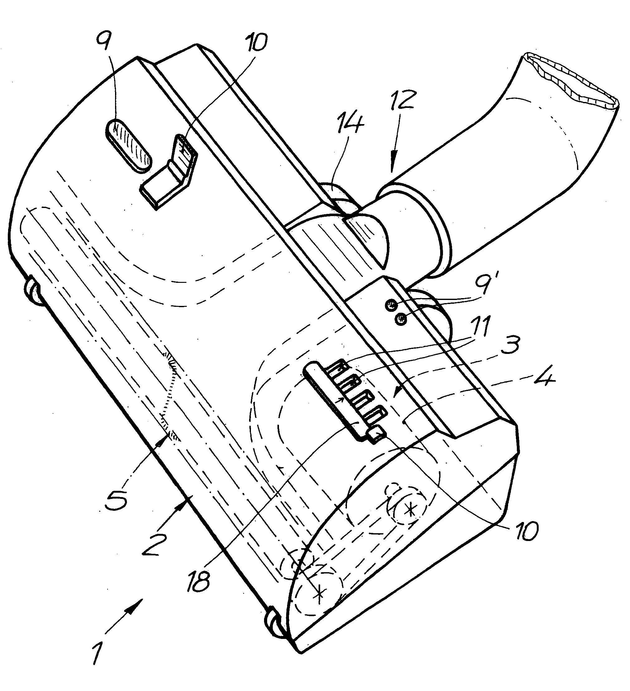
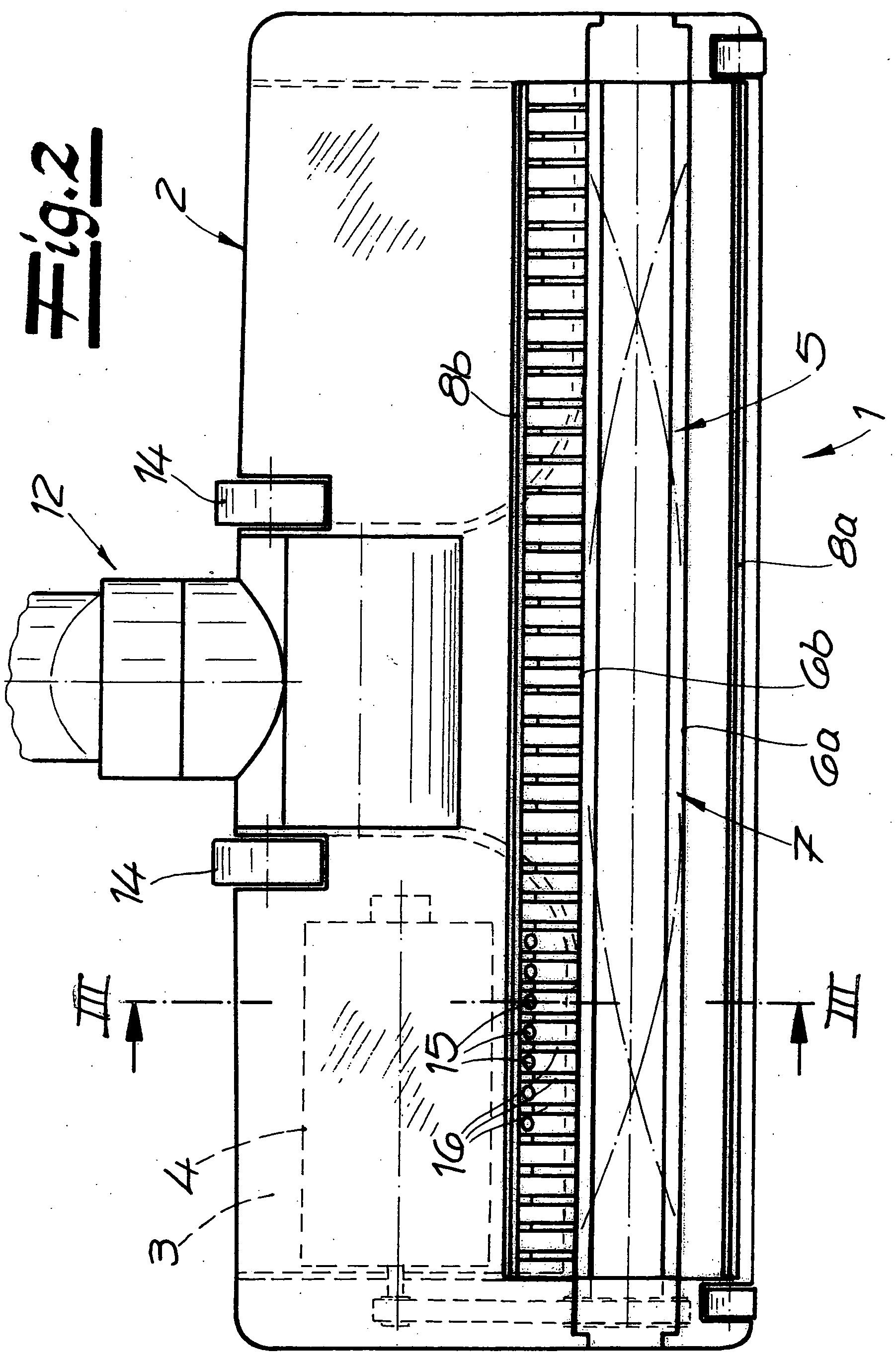
[0026]Referring now in detail to the drawings, FIG. 1 shows an electric vacuum head 1 according to the invention, in a perspective view. The electric vacuum head 1 has a housing 2, in which an electric motor 4 for driving a cleaning device 5 configured as a brush roller is disposed in a motor chamber 3. The bristles of the brush roller pass through a vacuum mouth 7 that runs on the underside of housing 2, over the width of the electric vacuum head 1, and is delimited by a front vacuum mouth edge 6a and a rear vacuum mouth edge 6b. Sealing lips 8a, 8b are disposed in front of front vacuum mouth edge 6a and behind rear vacuum mouth edge 6b, in the movement direction. In addition to display elements 9, 9′, and operating elements 10, air entry openings 11 of motor chamber 3, for passage of air to cool electric motor 4, can be seen at the top of the housing 2. Electric vacuum head 1 has a vacuum connector 12 for a connection to a suction tube 13 or a vacuum cleaner housing, configured as...


PUM


Abstract

An electric vacuum head for a vacuum cleaner has a housing, a cleaning device that can be driven by an electric motor disposed within the housing in a motor chamber, a vacuum mouth on the underside of the housing delimited by vacuum mouth edges, and a vacuum connector. The motor chamber has at least one air entry opening for entry of air to cool the electric motor, and at least one air exit opening. The air exit opening is disposed on the underside of the housing so that the cooling air that exits from the air exit opening during operation of the electric vacuum head enters into the vacuum mouth by way of at least one of the vacuum mouth edges.

Description

CROSS REFERENCE TO RELATED APPLICATIONS[0001]Applicants claim priority under 35 U.S.C. 119 of European Application No. 07 022 070.2 filed Nov. 14, 2007.BACKGROUND OF THE INVENTION[0002]1. Field of the Invention[0003]The invention relates to an electric vacuum head for a vacuum cleaner, having a housing, a cleaning device that can be driven by an electric motor disposed within the housing in a motor chamber, a vacuum mouth on the underside of the housing delimited by vacuum mouth edges, and a vacuum connector. The motor chamber has at least one air entry opening for entry of ambient air, and at least one air exit opening.[0004]The electric vacuum head can have a rechargeable battery or also an electrical connector to the voltage supply, by way of a vacuum cleaner. Without restriction, the electric vacuum head can be connected by way of a suction tube and a flexible hose, or directly to a vacuum cleaner housing. If the vacuum head is connected directly to the vacuum cleaner housing, t...

Claims


Application Information

Patent Timeline
IPC IPC(8): A47L9/02
CPCA47L9/04
Inventor DILGER, HORSTKAFFENBERGER, DIETERLIND, THOMASRIEHL, KLAUS-DIETERSTEUDTNER, HANS-JOACHIM
Owner WESSEL WERK
Why Eureka
Try Eureka