
Substrate processing apparatus

a processing apparatus and substrate technology, applied in the direction of transportation and packaging, pile separation, coating, etc., to achieve the effect of preventing slippage, securely and stably

Active Publication Date: 2009-05-07
KOKUSA ELECTRIC CO LTD
View PDF3 Cites 276 Cited by
  • Summary
  • Abstract
  • Description
  • Claims
  • Application Information

AI Technical Summary

Benefits of technology

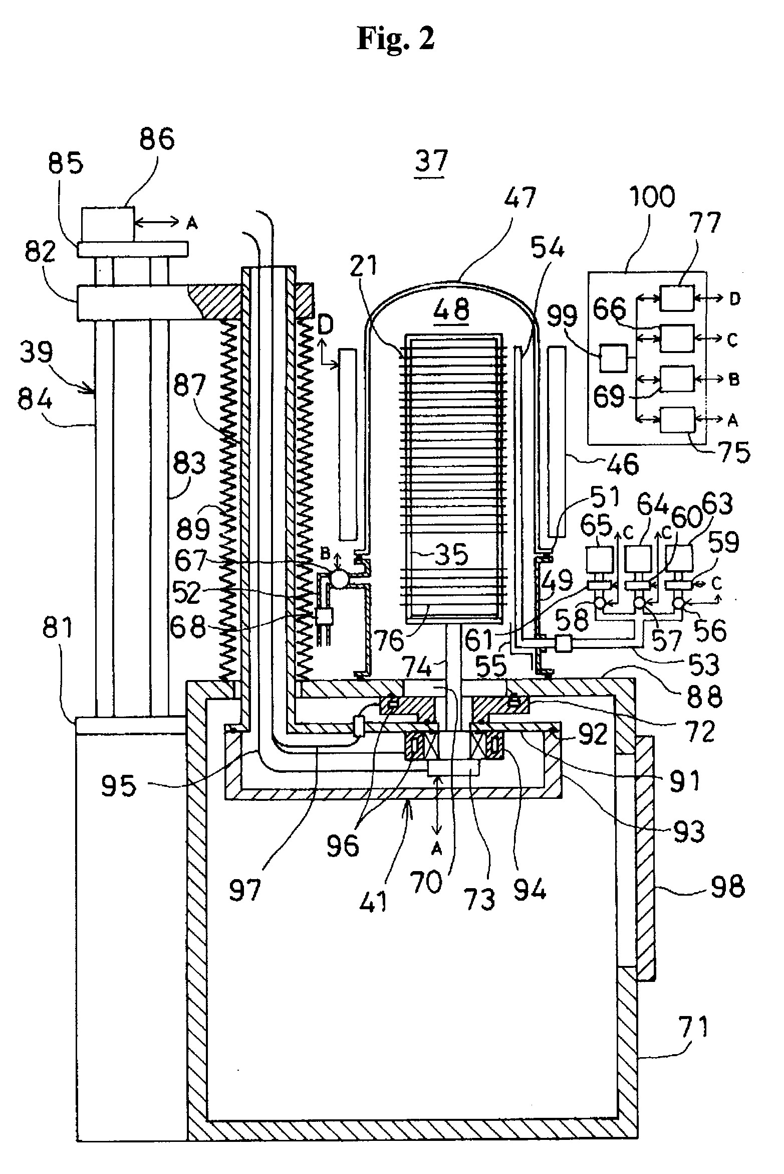
[0024]An object of the present invention is to provide a substrate processing apparatus, in which undesired loads are not applied to penetration parts of a gas nozzle and a temperature detector even when a reaction tube is inclined so that damages can be prevented, and the penetration parts can be firmly fixed for preventing slippage and supporting the gas nozzle and the temperature detector securely and stably.

Problems solved by technology

This causes problems in that the vertical parts of the gas nozzle 11 and the temperature detector 12 are dislocated away from the inner wall of the reaction tube 1 and are thus supported in an unstable state.

Method used


Image

  • Substrate processing apparatus
  • Substrate processing apparatus
  • Substrate processing apparatus

Examples


first embodiment

[0102]Hereinafter, structures of supporting parts for the gas nozzle 54 and the temperature detector 102 will be described with reference to FIG. 3 to FIG. 5 in accordance with a

[0103]The supporting parts for the gas nozzle 54 and the temperature detector 102 have approximately the same structure. The supporting part structure for the gas nozzle 54 will be first explained.

[0104]The gas nozzle 54 is an L-shaped tube made of quartz. The gas nozzle 54 includes a vertical part 54a extending along the inner wall of the reaction tube 47 and a horizontal part 54b welded to a lower end of the vertical part 54a.

[0105]The horizontal part 54b is horizontally inserted through the inlet flange 49, and a region of the gas nozzle 54 which has an insertion portion of the horizontal part 54b disposed inside of the processing chamber 48 and the lower end of the vertical part 54a is supported by the narrow tube supporting member 55.

[0106]The narrow tube supporting member 55 will now be described with...

second embodiment

[0117]With reference to FIG. 6 to FIG. 13, structures of supporting parts for the gas nozzle 54 and the temperature detector 102 will be described hereinafter in accordance with a

[0118]First, with reference to FIG. 6 and FIG. 8 to FIG. 11, the structure of the supporting part for the gas nozzle 54 will be explained. The same elements as those of the first embodiment are denoted by the same reference numerals, and descriptions thereof will be omitted.

[0119]As shown in FIG. 6, the internal flange 103 protrudes inwardly from the inner circumference of the lower side of the inlet flange 49 and has a two part structure. The internal flange 103 is configured by an inner rim 121 formed as part of the inlet flange 49 and a doughnut-shaped ring seat 122 configured to receive bolts from the bottom side of the inner rim 121.

[0120]As shown in FIG. 8 and FIG. 9, an A supporting member holder 123 and a B supporting member holder 124 are fixed to the ring seat 122 using bolts (not shown). Each of ...


PUM

PropertyMeasurementUnit
temperatureaaaaaaaaaa
corrosion-resistantaaaaaaaaaa

Abstract

Provided is a substrate processing apparatus. The substrate processing apparatus includes a reaction tube, a substrate holder, a gas nozzle, a heating unit, a temperature detector, and an exhaust unit. The reaction tube accommodates and processes substrates. The substrate holder holds substrates stacked at predetermined intervals in the reaction tube. The gas nozzle is installed along a stacked direction of the substrates. The heating unit heats the substrates. The temperature detector is installed along the stacked direction of the substrates. The exhaust unit exhausts an inside atmosphere of the reaction tube. Each of the gas nozzle and the temperature detector includes first and second parts and is supported by a narrow tube supporting member including first and second supporting parts. The first supporting part makes contact with the first part. The second supporting part is parallel with the second part and supports the second part.

Description

CROSS-REFERENCE TO RELATED PATENT APPLICATION[0001]This U.S. non-provisional patent application claims priority under 35 U.S.C. § 119 of Japanese Patent Application Nos. 2007-274005, filed on Oct. 22, 2007, and 2008-215943, filed on Aug. 25, 2008, in the Japanese Patent Office, the entire contents of which are hereby incorporated by reference.BACKGROUND OF THE INVENTION[0002]1. Field of the Invention[0003]The present invention relates to a substrate processing apparatus for performing a process, such as a thin film forming process, an oxidation process, a diffusion process, an annealing process, and an etching process, on a substrate such as a silicon wafer.[0004]2. Description of the Prior Art[0005]Examples of substrate processing apparatuses include a single wafer type substrate processing apparatus configured to process substrates one by one and a batch type substrate processing apparatus configured to process a predetermined number of substrates at a time.[0006]A batch type subs...

Claims


Application Information

Patent Timeline
Patent Type & Authority Applications(United States)
IPC IPC(8): H01L21/02H01L21/67
CPCH01L21/67248H01L21/67109
Inventor MARUBAYASHI, TETSUYAINOKUCHI, YASUHIRO
Owner KOKUSA ELECTRIC CO LTD
Learn More