
Low power, low noise amplifier system

a low-power amplifier and low-noise technology, applied in the direction of low-noise amplifiers, amplifiers with semiconductor devices/discharge tubes, positive-feedback circuit arrangements, etc., can solve the problems of low and near-d.c. frequency performance, small current, and easy overflow of stray noise current, so as to improve low-noise, low-power amplifier systems

Active Publication Date: 2009-05-07
ANALOG DEVICES INC
View PDF6 Cites 26 Cited by
  • Summary
  • Abstract
  • Description
  • Claims
  • Application Information

AI Technical Summary

Benefits of technology

[0004]It is therefore an object of this invention to provide an improved low noise, low power amplifier system.
[0005]It is a further object of this invention to provide such an improved low noise, low power amplifier system which is capable of precisely amplifying even low, and near d.c. frequencies and even d.c.
[0006]It is a further object of this invention to provide such an improved low noise, low power amplifier system which employs a differential approach and can independently control input common mode and output common mode levels.
[0007]It is a further object of this invention to provide such an improved low noise, low power amplifier system which has high input common mode rejection.
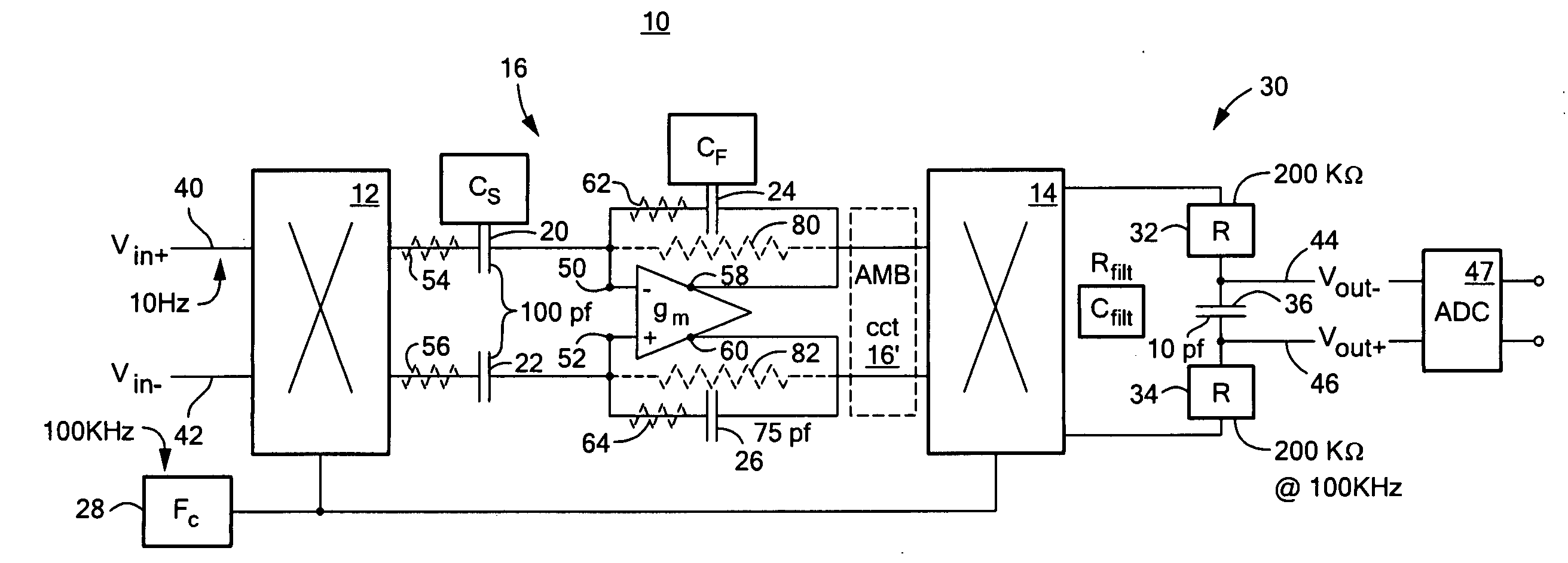
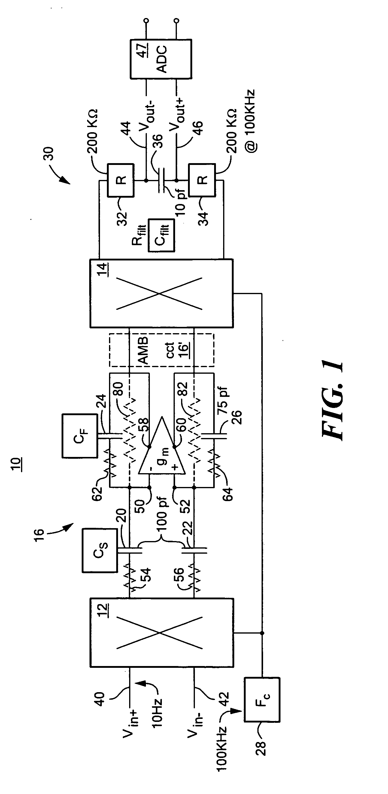
[0011]This invention features a low power, low noise amplifier system including at least one amplifier having first and second differential input terminals, first and second differential output terminals and providing a differential output. First and second input capacitors are interconnected with the first and second differential amplifier input terminals. First and second feedback circuits containing first and second feedback capacitors, respectively, are interconnected with the amplifier differential input and output terminals. An input chopper switch circuit receives a low frequency differential input and selectively, alternately swaps those low frequency differential inputs through the input capacitors to the differential input terminals of the amplifier. An output chopper switch receives and selectively, alternately swaps the amplifier differential outputs synchronously with the input chopper switch circuit. A low pass filter responsive to the swapped differential outputs provides a low noise, low power amplification of the low frequency differential inputs.

Problems solved by technology

One shortcoming of such devices is that they do not perform well at low and near d.c. frequencies.
If a low frequency signal is introduced into a capacitor the current will be very small and easily overwhelmed by stray noise current.

Method used


Image

  • Low power, low noise amplifier system
  • Low power, low noise amplifier system
  • Low power, low noise amplifier system

Examples


Embodiment Construction

[0022]Aside from the preferred embodiment or embodiments disclosed below, this invention is capable of other embodiments and of being practiced or being carried out in various ways. Thus, it is to be understood that the invention is not limited in its application to the details of construction and the arrangements of components set forth in the following description or illustrated in the drawings. If only one embodiment is described herein, the claims hereof are not to be limited to that embodiment. Moreover, the claims hereof are not to be read restrictively unless there is clear and convincing evidence manifesting a certain exclusion, restriction, or disclaimer.

[0023]There is shown in FIG. 1 an improved low power, low noise amplifier system 10, according to this invention which includes an input chopper switch circuit 12, also known as a swapper or cross point switch and an output chopper switch circuit 14. Between chopper switch circuits 12 and 14 is a capacitive gain amplifier c...


PUM


Abstract

A low power, low noise amplifier system includes at least one amplifier having first and second differential input terminals, first and second differential output terminals and providing a differential output; first and second input capacitors interconnected with the first and second differential amplifier input terminals; first and second feedback circuits containing first and second feedback capacitors, respectively, interconnected with the amplifier differential input and output terminals; an input chopper switch circuit for receiving a low frequency differential input and selectively, alternately swapping those low frequency differential inputs through the input capacitors to the differential input terminals of the amplifier; an output chopper switch for receiving and selectively, alternately swapping the amplifier differential outputs synchronously with the input chopper switch circuit; and a low pass filter responsive to the swapped differential outputs for providing a low noise, low power amplification of the low frequency differential inputs.

Description

RELATED APPLICATIONS[0001]This application claims benefit of and priority to U.S. Provisional Application Ser. No. 60 / 993,745 filed Sep. 14, 2007 and 60 / 994,077 filed Sep. 17, 2007 which are incorporated herein by this reference.FIELD OF THE INVENTION[0002]This invention relates to an improved low noise, low power amplifier system and more particularly to such an improved low noise, low power amplifier system which enables more precise control over gain levels.BACKGROUND OF THE INVENTION[0003]Amplifiers with capacitor defined gain have advantages over resistor implemented amplifiers as capacitors do not introduce noise as resistors do nor do they introduce the self heating problem that resistors do. Capacitor implemented amplifiers are very stable and if the signal varies slowly e.g. 100 Hz there can be generally a naturally high input impedance. They are also easy to drive using lower current. One shortcoming of such devices is that they do not perform well at low and near d.c. fre...

Claims


Application Information

Patent Timeline
IPC IPC(8): H03F3/45H03F1/38
CPCH03F3/387H03F3/45475H03F2203/45526H03F2203/45134H03F2203/45521H03F2200/294
Inventor LYDEN, COLIN G.BIRK, CHRISTIAN S.TANSLEY, TOMAS
Owner ANALOG DEVICES INC
Learn More