Catch base for attaching catch of snap fastener
- Summary
- Abstract
- Description
- Claims
- Application Information
AI Technical Summary
Benefits of technology
Problems solved by technology
Method used
Image
Examples
first embodiment
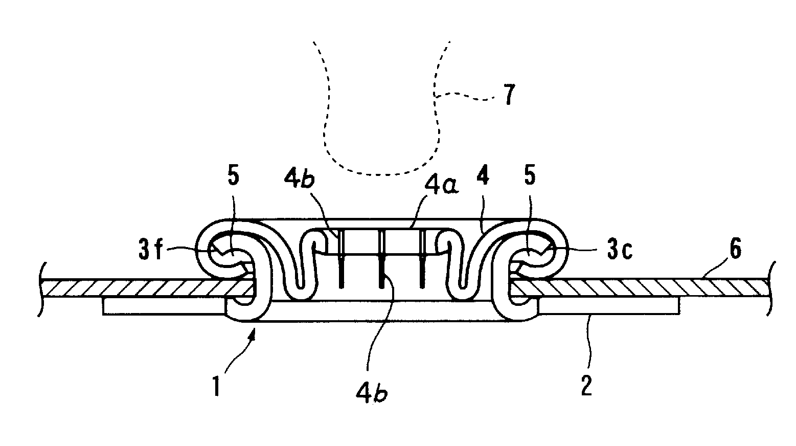
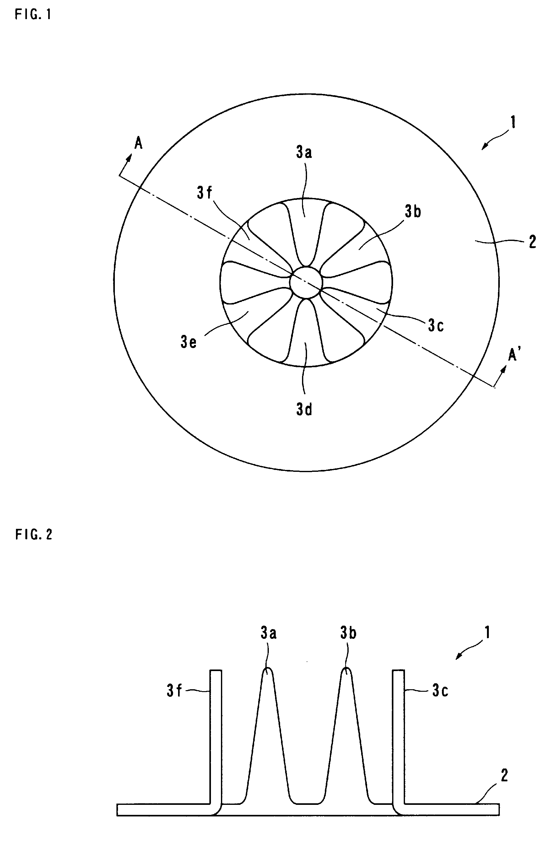
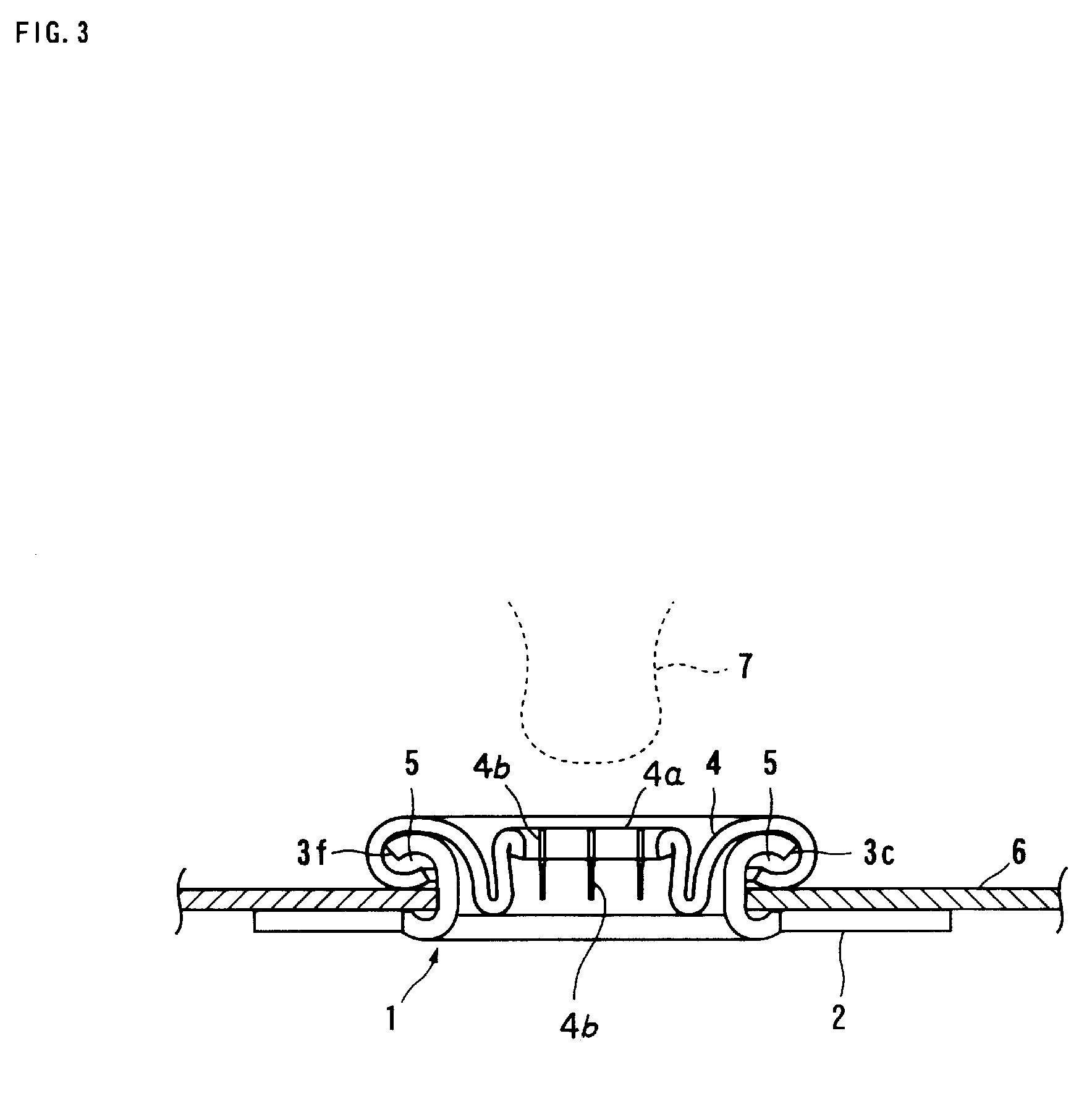
[0019]A catch base according to an embodiment of the present invention will now be described in detail with reference to FIGS. 1 to 3. FIG. 1 is a plan view of a metallic disk having claws formed by punching using a press. FIG. 2 is a side view of the catch base whose claws are raised by 90°. FIG. 3 illustrates a catch attached to a cloth using the catch base according to the embodiment of the present invention. In FIGS. 1 to 3, a catch base 1 includes a body 2 and six claws 3a to 3f formed by punching such that ends of the claws 3a to 3f face the center of the body 2. In order to use the catch base 1 as a product, the claws 3a to 3f are raised by 90° as shown in FIG. 2.
[0020]As shown in FIG. 3, a catch 4 is put on one side of a cloth 6, and the claws 3a to 3f of the catch base 1 having the above-described structure are fitted into catching portions 5 of the catch 4 from the other side of the cloth 6.
[0021]The catch base 1 is then pressed into contact with the catch 4 while the clot...
PUM
| Property | Measurement | Unit |
|---|---|---|
| Fraction | aaaaa | aaaaa |
| Angle | aaaaa | aaaaa |
Abstract
Description
Claims
Application Information
 - R&D
- Intellectual Property
- Life Sciences
- Materials
- Tech Scout
- Unparalleled Data Quality
- Higher Quality Content
- 60% Fewer Hallucinations
Browse by: Latest US Patents, China's latest patents, Technical Efficacy Thesaurus, Application Domain, Technology Topic, Popular Technical Reports.
© 2025 PatSnap. All rights reserved.Legal|Privacy policy|Modern Slavery Act Transparency Statement|Sitemap|About US| Contact US: help@patsnap.com


