
Rechargeable battery

a rechargeable battery and battery technology, applied in the direction of secondary cell servicing/maintenance, cell components, cell component details, etc., can solve the problems of inaccurate and precise molding resin formation, increase defects, unsatisfactory effects, etc., and achieve the effect of improving the welding strength of lead plates

Inactive Publication Date: 2009-04-30
SAMSUNG SDI CO LTD
View PDF3 Cites 11 Cited by
  • Summary
  • Abstract
  • Description
  • Claims
  • Application Information

AI Technical Summary

Benefits of technology

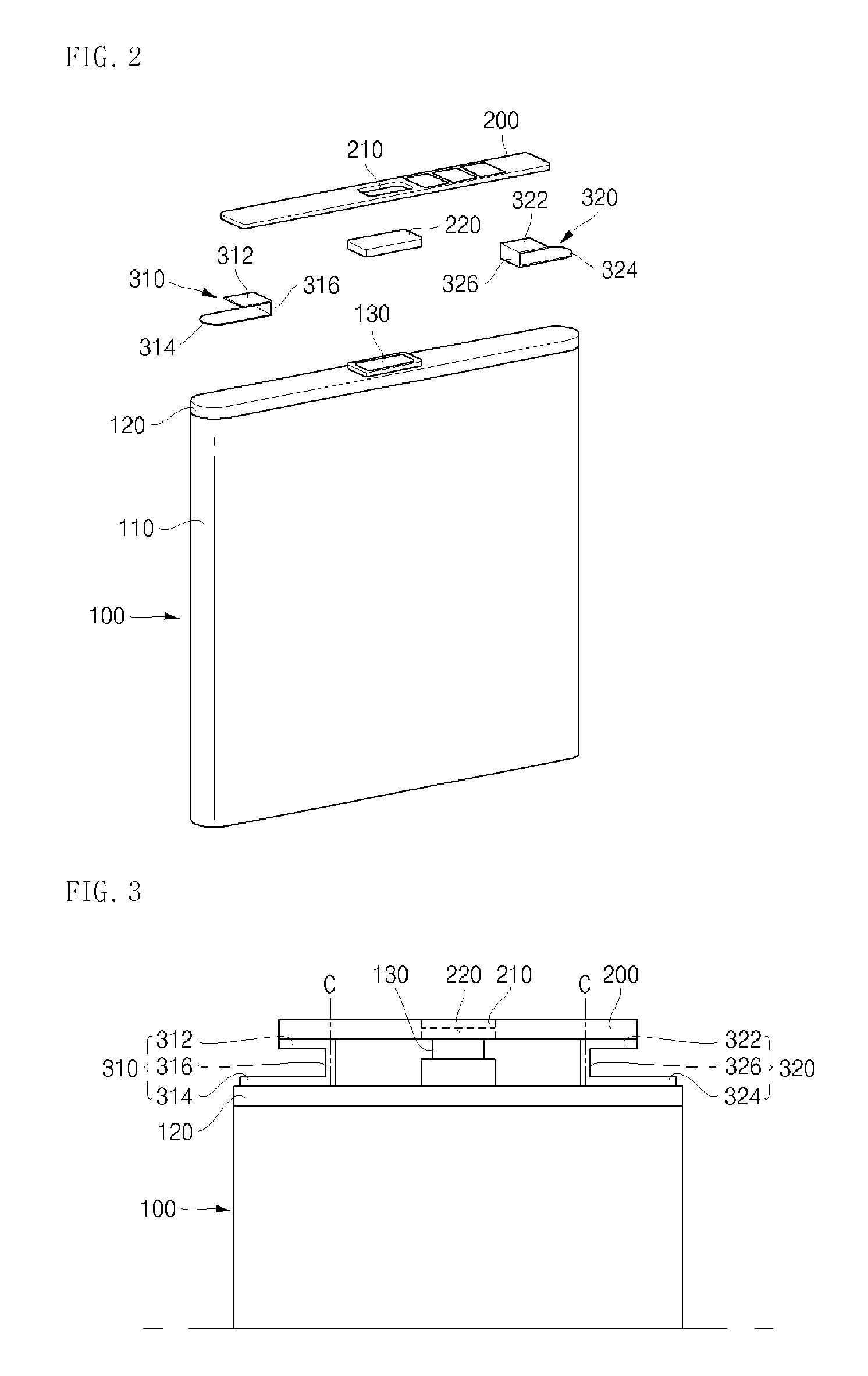
The present invention provides a rechargeable battery with a lead plate that improves the welding strength of the connection between a protection circuit board and a bare cell. The lead plate has a substrate fixing part attached to the protection circuit board, a bare cell fixing part attached to the bare cell, and a connection part that connects the substrate and bare cell fixing parts. The lead plate is installed with the connection part positioned between the protection circuit board and the bare cell. The substrate and bare cell fixing parts may be folded in the same or opposite directions about the connection part. The bare cell fixing part may be fixed to the bare cell by laser welding. The lead plate is made of nickel or nickel alloy. The technical effect of the invention is to enhance the reliability and durability of the battery connection.

Problems solved by technology

The method of fixing the protect circuit module to the bare cell by molding the melted resin is performed at a high temperature which produces undesirable effects on various elements included in the protect circuit module.
Further, there is a disadvantage that it is difficult to accurately and precisely form a molding resin at an exact position on an upper surface of the bare cell, thereby increasing defects.
As such, the force exerted on the protection circuit board by the lead plate is not uniform.
When the lead plate is welded without being in contact with the upper surface of the cap plate as above, a gap is generated between the lead plate and the cap plate, thereby causing weld defects.
Accordingly, a welding strength of the lead plate fixed to the upper surface of the cap plate is decreased, thereby lowering quality of products.

Method used


Image

  • Rechargeable battery
  • Rechargeable battery
  • Rechargeable battery

Examples


Embodiment Construction

[0023]Reference will now be made in detail to the present embodiments of the present invention, examples of which are illustrated in the accompanying drawings, wherein like reference numerals refer to the like elements throughout. The embodiments are described below in order to explain the present invention by referring to the figures.

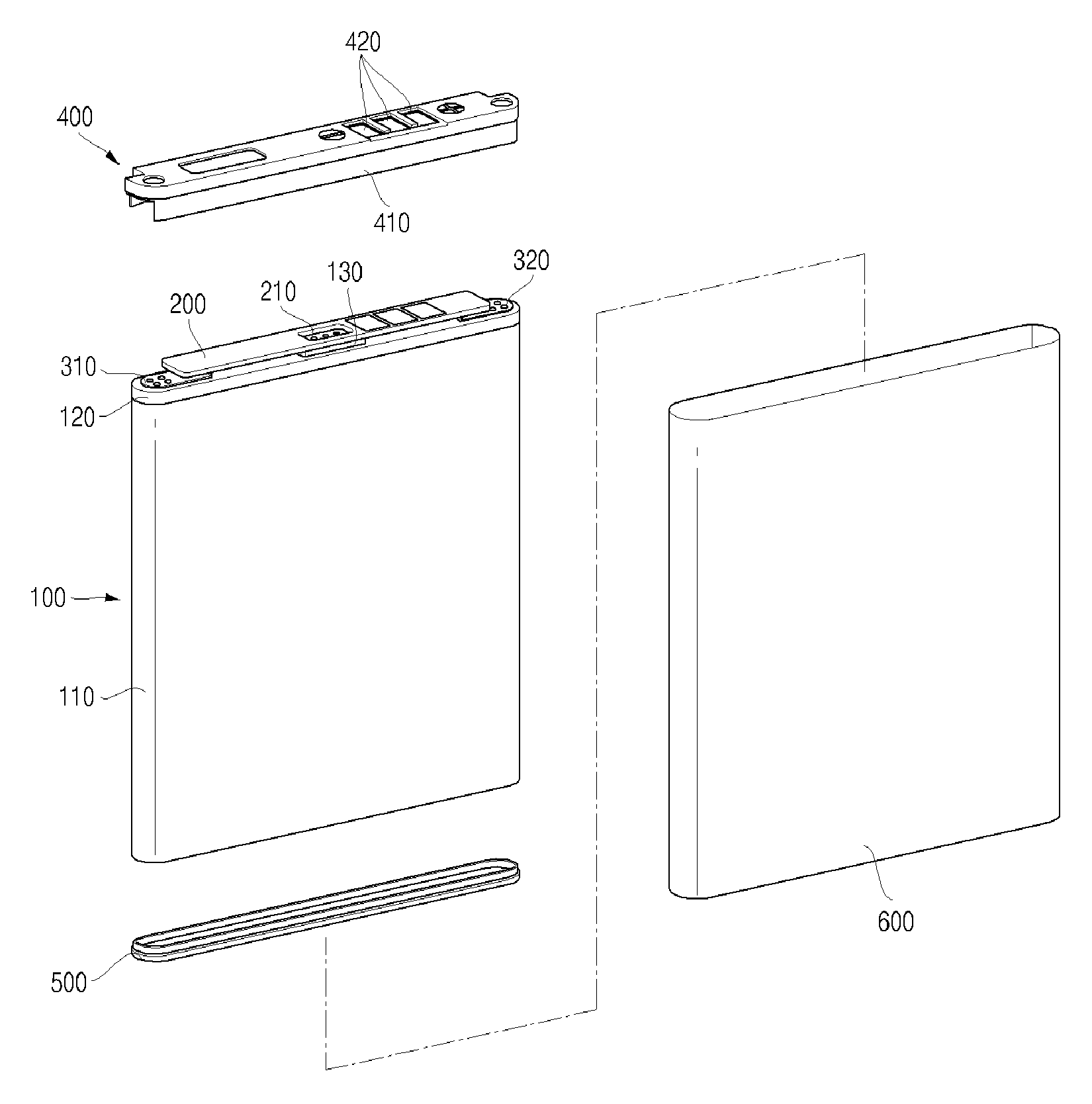
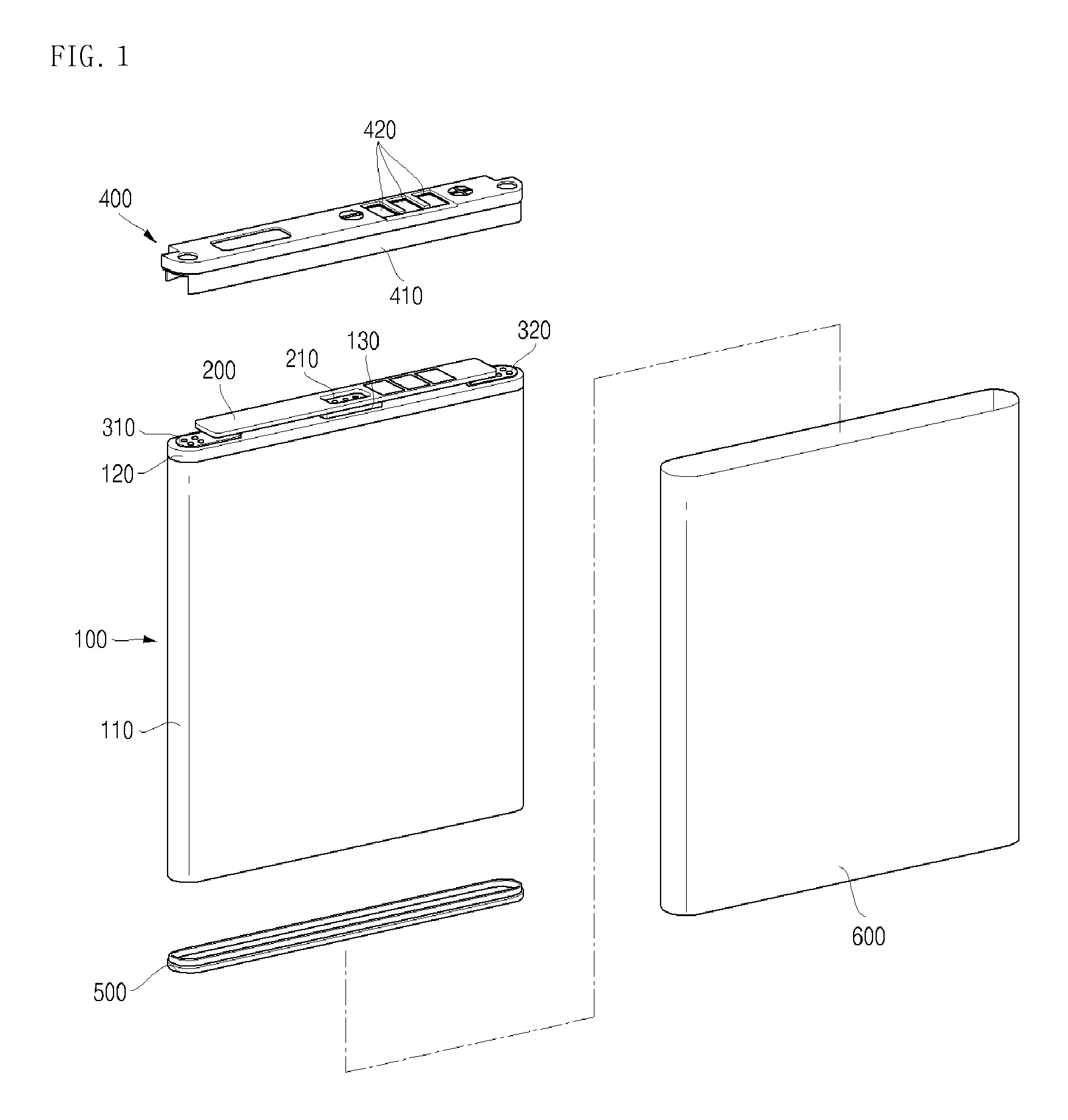
[0024]FIG. 1 is an exploded perspective view illustrating a rechargeable battery according to aspects of the present invention. FIG. 2 is an exploded perspective view illustrating a bare cell and a protection circuit board of the rechargeable battery. FIG. 3 is a front view illustrating the rechargeable battery.

[0025]Referring to FIGS. 1 to 3, the rechargeable battery includes a rechargeable bare cell 100, a protection circuit board 200 installed on an upper surface of the bare cell 100, lead plates 310 and 320 disposed between the protection circuit board 200 and bare cell 100 so as to electrically couple them, an upper cover 400 installed so as to co...


PUM

PropertyMeasurementUnit
shapeaaaaaaaaaa
electricallyaaaaaaaaaa
lengthaaaaaaaaaa

Abstract

A rechargeable battery includes: a bare cell; a protection circuit board installed on an upper surface of the bare cell; and a lead plate to connect the protection circuit board with the bare cell, wherein the lead plate includes a substrate fixing part fixed to the protection circuit board, a bare cell fixing part fixed to the bare cell, and a connection part to connect the substrate fixing part with the bare cell fixing part, the lead plate being installed such that the connection part is disposed between the protection circuit board and the upper surface of the bare cell. A welding strength is improved when the lead plate connecting the bare cell with the protection circuit board is installed, thereby prominently reducing defects in manufacturing packs and modules.

Description

CROSS-REFERENCE TO RELATED APPLICATION[0001]This application claims the benefit of Korean Application No. 2007-109201 filed on Oct. 29, 2007 in the Korean Intellectual Property Office, the disclosure of which is incorporated herein by reference.BACKGROUND OF THE INVENTION[0002]1. Field of the Invention[0003]Aspects of the present invention relate to a rechargeable battery, and more particularly, to a rechargeable battery which can improve performance and reliability of the battery by improving its assembly structure.[0004]2. Description of the Related Art[0005]Generally, a rechargeable battery is a battery in which a voltage potential may be reestablished after having depleted the previous voltage potential stored therein while a disposable battery is not rechargeable. The rechargeable battery has been widely used in the fields of the advanced electronic devices, such as in cellular phones, notebook computers, and camcorders. Particularly, a lithium rechargeable battery has an opera...

Claims


Application Information

Patent Timeline
Patent Type & Authority Applications(United States)
IPC IPC(8): H01M2/00H01M10/052H01M10/36H01M50/147
CPCH01M10/052H01M10/425Y02E60/10H01M50/103H01M50/147H01M50/528H01M50/20H01M50/10
Inventor JANG, YOUNGCHEOLSEO, KYUNGWONBYUN, JEONGDEOKKWAK, EUNOK
Owner SAMSUNG SDI CO LTD
Learn More