
Burn protective materials

Inactive Publication Date: 2009-04-30
WL GORE & ASSOC INC
View PDF38 Cites 29 Cited by
  • Summary
  • Abstract
  • Description
  • Claims
  • Application Information

AI Technical Summary

Benefits of technology

[0004]In one embodiment, a material is described that is suitable for use in garments for workers in hazardous environments, which is breathable, waterproof, and flame resistant, while being lightweight, comfortable to wear, flexible, and affordable. In one embodiment method is provided for reducing the afterflame of a flammable, meltable material to less than 20 seconds, comprising providing an outer textile comprising a flammable, meltable material, and comprising an inner side and an outer side; providing a heat reactive material comprising a polymer resin-expandable graphite mixture, wherein the expandable graphite has an expansion of at least 900 μm upon heating to 280° C.; applying the polymer-expandable graphite mixture to the inner surface of the outer textile material to form the heat reactive material, wherein the outer side of the outer textile is exposed to a flame.

Problems solved by technology

These fibers may be inherently flame resistant but may have several limitations.
Specifically, these fibers may be very expensive, difficult to dye and print, and may not have adequate abrasion resistance.
Additionally, these fibers pick up more water and offer unsatisfactory tactile comfort as compared to nylon or polyester based fabrics.

Method used


Image

  • Burn protective materials
  • Burn protective materials
  • Burn protective materials

Examples


fabric example 1

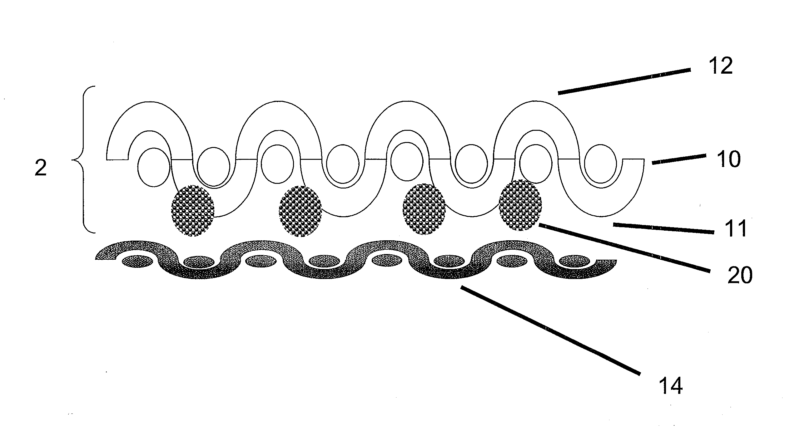
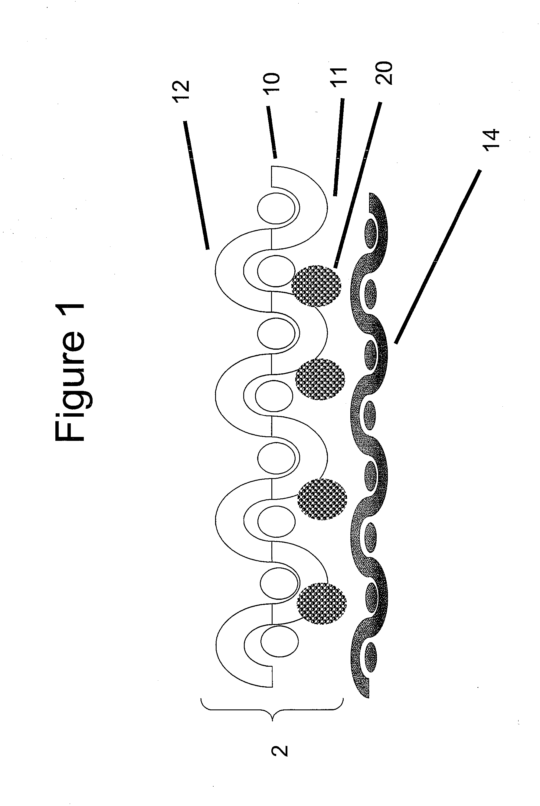
[0070]A textile comprising heat reactive material was prepared as follows. A 130 gsm nylon 6,6 knit outer textile (10) from Milliken Corporation, Spartanburg, S.C. (STYLE 755133) was coated with discrete dots of the polymer resin-expandable graphite mixture 1 by a gravure roller (at about 100° C. with a pressure of about 40 psi) in such a manner as to provide coverage of approximately 32 percent on the surface of the fabric, with a laydown of about 35 grams per square meter (gsm). The gravure roll had a round dot pattern with a cell depth about 1200 um, cell opening of about 2500 um, and a spacing of about 2500 um.

[0071]The coated fabric was allowed to cure at 50% RH and 23° C. for 48 hours. Samples of the textile coated with the polymer resin-graphite mixture 1 were tested as per self extinguishing test described herein recorded an afterflame of less than 5 seconds.

example 1

Laminate Example 1

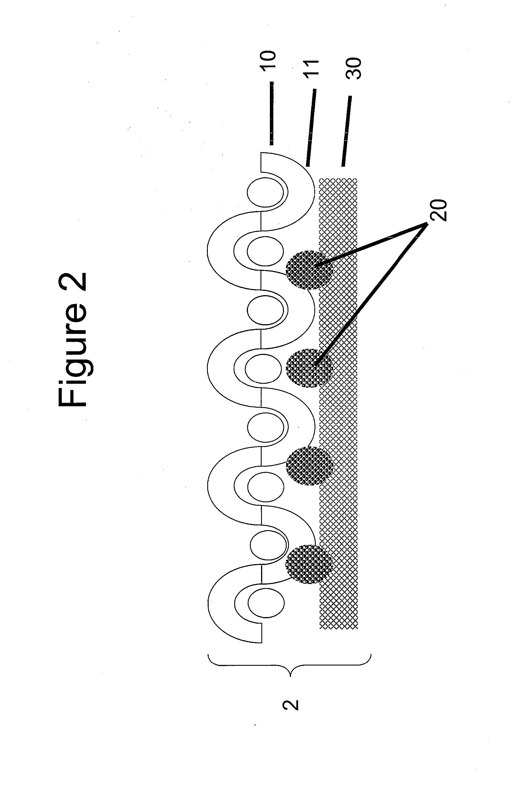
[0072]A laminate was made using a 95 gsm nylon 6,6 plain weave outer textile from Milliken (part number 131967) and thermally stable convective barrier 1, substantially as depicted in FIG. 2. The laminate was constructed by printing discrete dots of the Polymer Resin-Expandable Graphite Mixture 1 onto thermally stable convective barrier 1 and then adhering the 95 gsm nylon woven outer textile to the thermally stable convective barrier using a nip pressure of about 30 psi. The discrete dots of heat reactive material (20) were printed by a gravure roller as described above.

[0073]The resultant laminate was a two layer laminate of a thermally stable convective barrier and a nylon woven meltable outer textile layer bonded by dots of polymer resin-expandable graphite mixture 1. The laminate was taken up onto a steel drum under tension and allowed to cure for about 48 hours at greater than about 50% relative humidity.

[0074]Samples were tested according to MVTR, Horizontal...

example 2

Laminate Example 2

[0075]A two layer laminate was made substantially according to Example 1, except that thermally stable convective barrier 2, described above, was used in place of thermally stable convective barrier 1

[0076]Samples were tested according to the Horizontal Flame Test and Self-Extinguishing Test methods, described herein and reported in Table 1.


PUM

PropertyMeasurementUnit
Temperatureaaaaaaaaaa
Lengthaaaaaaaaaa
Fractionaaaaaaaaaa

Abstract

A method is described for reducing the afterflame of a flammable, meltable material. A textile composite is described comprising an outer textile comprising a flammable, meltable material, and a heat reactive material comprising a polymer resin-expandable graphite mixture.

Description

BACKGROUND OF THE INVENTION[0001]In order to reduce fire related burn injuries, protective clothing is desired for professionals working in hazardous environments where short duration exposure to fire is possible, such as search and rescue, and police. Protective gear for workers exposed to these conditions should provide some enhanced protection to allow the wearer to get away from the hazard quickly and safely, rather than to combat the hazard.[0002]Traditionally, flame resistant protective garments have been made with an outermost layer comprising non-combustible, non-melting fabric made of, for example, aramids, polybenzimidazole (PBI), poly p-phenylene-2,6-bezobisoxazole (PBO), modacrylic blends, polyamines, carbon, polyacrylonitrile (PAN), and blends and combinations thereof. These fibers may be inherently flame resistant but may have several limitations. Specifically, these fibers may be very expensive, difficult to dye and print, and may not have adequate abrasion resistance...

Claims


Application Information

Patent Timeline
IPC IPC(8): B29C65/02B05D3/08B32B7/00
CPCA41D31/0027Y10T156/10B32B27/12D06M11/74D06M15/564D06M23/16D06M2101/32D06M2101/34D06M2200/30D06N3/0063A43B23/0205B32B27/20B32B27/40B32B2264/108B32B2307/308B32B2437/00Y10T428/269B32B5/18A41D31/085Y10T442/291Y10T442/696Y10T442/2631Y10T442/2648Y10T442/2893Y10T442/2918Y10T442/2738Y10T442/2902
Inventor PANSE, DATTATREYA
Owner WL GORE & ASSOC INC
Learn More