
Method and apparatus for high-pressure atomic-beam laser induced deposition/etching

a laser induced deposition and high-pressure technology, applied in the field of atomic, molecular and nanoparticle deposition techniques, can solve the problems of limiting the deposition rate and quality of deposits, causing more recombination events, and causing spall

Inactive Publication Date: 2009-04-30
LOS ALAMOS NATIONAL SECURITY
View PDF11 Cites 3 Cited by
  • Summary
  • Abstract
  • Description
  • Claims
  • Application Information

AI Technical Summary

Benefits of technology

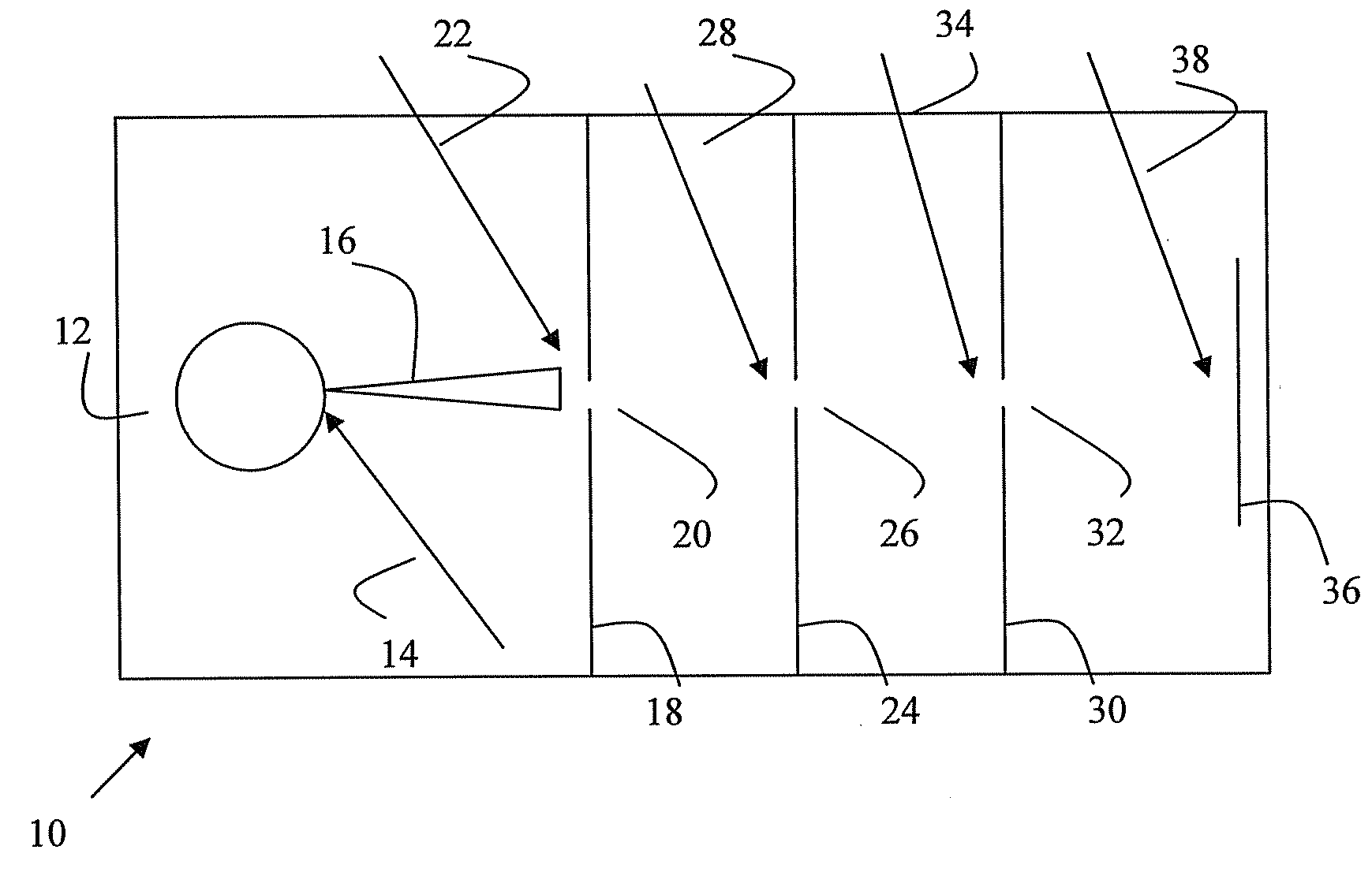
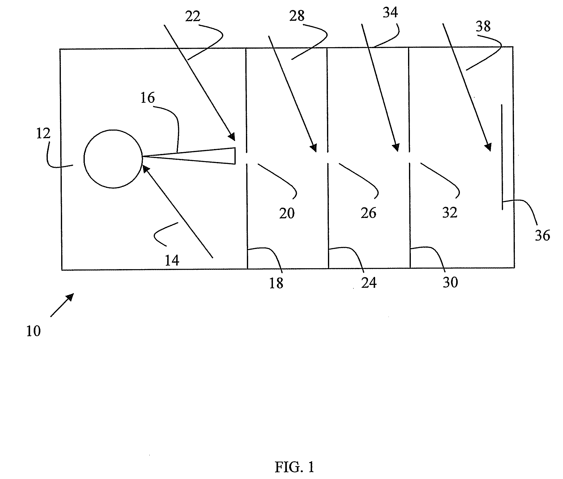
[0008]Another embodiment relates to a method for carrying out laser-induced atomic / molecular beam deposition. The method comprises: (1) providing a flow of chemical precursor, (2) providing a target within the flow of chemical precursor, having a desired composition, (3) irradiating the target with a laser beam to provide a plume of target material, (4) directing the plume in a desired direction by use of the flow of chemical precursor, (5) passing the precursor and plume of target material through an aperture into a region of lower pressure, (6) irradiating the plume and precursor to create an atomic / molecular beam, (e.g. to reduce the amount of agglomerated particles in the plume or to partially decompose the precursor), (7) directing the atomic / molecular beam onto a substrate to produce a deposition product, and (8) (optional) irradiating the location where the atomic / molecular beam impinges on the substrate to further decompose the atomic / molecular beam or to produce a specific deposit composition, stochiometry, or crystal structure.

Problems solved by technology

However, PLD has the disadvantage of “spall,” i.e. ejecting nano- to micro-scale particulates that travel with the plume to become embedded in the newly-formed deposit.
In addition, increasing the operating pressure and throughput of a PLD system tends to result in more recombination events.
Ultimately, this limits the deposition rate and quality of the deposits that can be created by PLD systems.
The primary disadvantages of CVD methods are: (1) the deposition rate may be very slow, as the process is often maintained at low pressures to reduce homogeneous nucleation, (2) undesired byproducts can be incorporated into the deposit material, (3) obtaining a correct deposit stochiometry is difficult with multi-component systems, (4) the deposit uniformity, composition and crystal structure may depend strongly on the local substrate temperature or other process conditions, and (5) it is difficult (even with plasma enhanced CVD), to ensure that only certain chemical species are present during the reaction, which can influence the ultimate composition / structure of the deposit material.

Method used


Image

  • Method and apparatus for high-pressure atomic-beam laser induced deposition/etching
  • Method and apparatus for high-pressure atomic-beam laser induced deposition/etching

Examples


Embodiment Construction

[0010]Using a focused short-pulse laser beam (i.e., less than about 1 fs to more than about 100 ps), a very high-temperature plasma is created at an aperture through which chemical precursors are flowing. While the chemical precursors are usually gases, they may also be liquids or super-critical fluids). These chemical precursors would typically be Chemical vapor deposition precursors or etchants, e.g. methane, trimethylamine alane, silane, chlorine, etc. Reactive gases, e.g. hydrogen or nitrogen, or inert carrier gases, such as Argon or Krypton may also be used. Adjacent to the aperture, a target comprised of a desired deposition material is placed such that a portion of the short-pulse beam is focused on the target and a plume of target material enters the flow of precursor / reactive / inert gases. Alternatively, nanoparticles of desired deposit material can be created through homogeneous nucleation using a laser beam in a separate chamber (e.g. through photolysis) and carried by the...


PUM

PropertyMeasurementUnit
electrical potentialaaaaaaaaaa
timeaaaaaaaaaa
magnetic fieldaaaaaaaaaa

Abstract

A method for carrying out pulsed laser deposition is disclosed. The method comprises providing a target having a desired composition; irradiating the target with a pulsed laser beam to provide a plume of target material; and directing the plume in a desired direction by use of an inert carrier gas. The plume of target material is passed through an aperture to create an atomic beam. One or both of the plume or the atomic beam is irradiated to reduce the amount of agglomerated particles in the atomic beam. The atomic beam is directed onto a substrate to produce a deposition product. An apparatus for carrying out the method is also disclosed.

Description

STATEMENT REGARDING FEDERAL RIGHTS[0001]This invention was made with government support under Contract No. DE-AC52-06NA25396 awarded by the U.S. Department of Energy. The government has certain rights in the invention.BACKGROUND OF INVENTION[0002]The present application relates generally to atomic, molecular, and nanoparticle deposition techniques. More particularly, the application relates to high-pressure, atomic, molecular, and nanoparticle beam deposition.[0003]A variety of methods for depositing thin-film coatings have been developed over the last half-century, including chemical vapor deposition, physical vapor deposition (e.g. sputtering, e-beam evaporation, IBAD, etc.), and pulsed laser deposition. Each has its advantages / disadvantages, depending on the material to be deposited, the substrate involved, and the desired material structure.[0004]Of these coating methods, Pulsed Laser Deposition (PLD) has the advantage that materials can be stochiometrically-deposited, so that t...

Claims


Application Information

Patent Timeline
Patent Type & Authority Applications(United States)
IPC IPC(8): C23C16/48C23C16/44
CPCC23C14/3435
Inventor MAXWELL, JAMES L.SPRINGER, ROBERT W.
Owner LOS ALAMOS NATIONAL SECURITY
Learn More