
Composition and Method for Controlling Excessive Exhaust Gas Temperatures

Active Publication Date: 2009-04-30
FORD GLOBAL TECH LLC
View PDF11 Cites 25 Cited by
  • Summary
  • Abstract
  • Description
  • Claims
  • Application Information

AI Technical Summary

Benefits of technology

[0003]Increases in exhaust temperature, such as during DPF regeneration, may result in self-sustained and self-induced temperature increase, thus increasing the temperature of the emissions control system past acceptable levels and thereby degrading aftertreatment catalysts including diesel particulate filters, lean NOx traps, in-situ Lean NOx Trap and SCR catalysts, decreasing the lifespan and effectiveness of such filters and catalysts. In particular, once DPF regeneration is commenced, the heat of that regeneration can further ignite additional regeneration, thereby leading to self-sustained and rapidly increasing regeneration rates and significantly increased temperatures.

Problems solved by technology

However, collection of particulate matter on the DPF increases back pressure in the exhaust system, decreasing fuel economy.
Increases in exhaust temperature, such as during DPF regeneration, may result in self-sustained and self-induced temperature increase, thus increasing the temperature of the emissions control system past acceptable levels and thereby degrading aftertreatment catalysts including diesel particulate filters, lean NOx traps, in-situ Lean NOx Trap and SCR catalysts, decreasing the lifespan and effectiveness of such filters and catalysts.
In particular, once DPF regeneration is commenced, the heat of that regeneration can further ignite additional regeneration, thereby leading to self-sustained and rapidly increasing regeneration rates and significantly increased temperatures.
For example, exhaust air flow may carry heat away from the exhaust system, but may not provide sufficient cooling to reduce self-sustained and self-induced temperature increases.
Additionally, it may not be clear in advance of self-sustained and self-induced temperature increases if certain operating conditions will allow enough air flow to cool the DPF.
However, decreasing combustion may stall or stop regeneration prematurely, thereby decreasing the effectiveness of the regeneration, defeating the purpose of the filter and increasing fuel consumption inefficiencies.
Further, the reduction of oxygen necessary to limit temperature may lead to excessive smoking in the engine.

Method used


Image

  • Composition and Method for Controlling Excessive Exhaust Gas Temperatures
  • Composition and Method for Controlling Excessive Exhaust Gas Temperatures
  • Composition and Method for Controlling Excessive Exhaust Gas Temperatures

Examples


Embodiment Construction

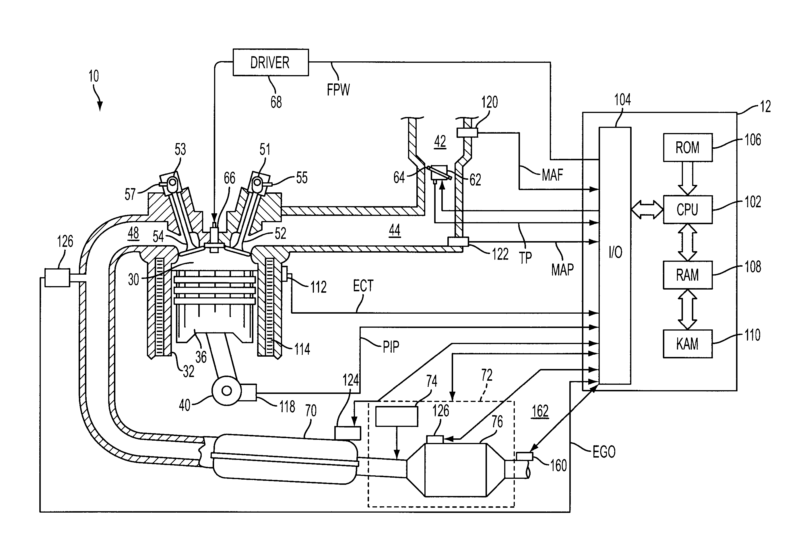
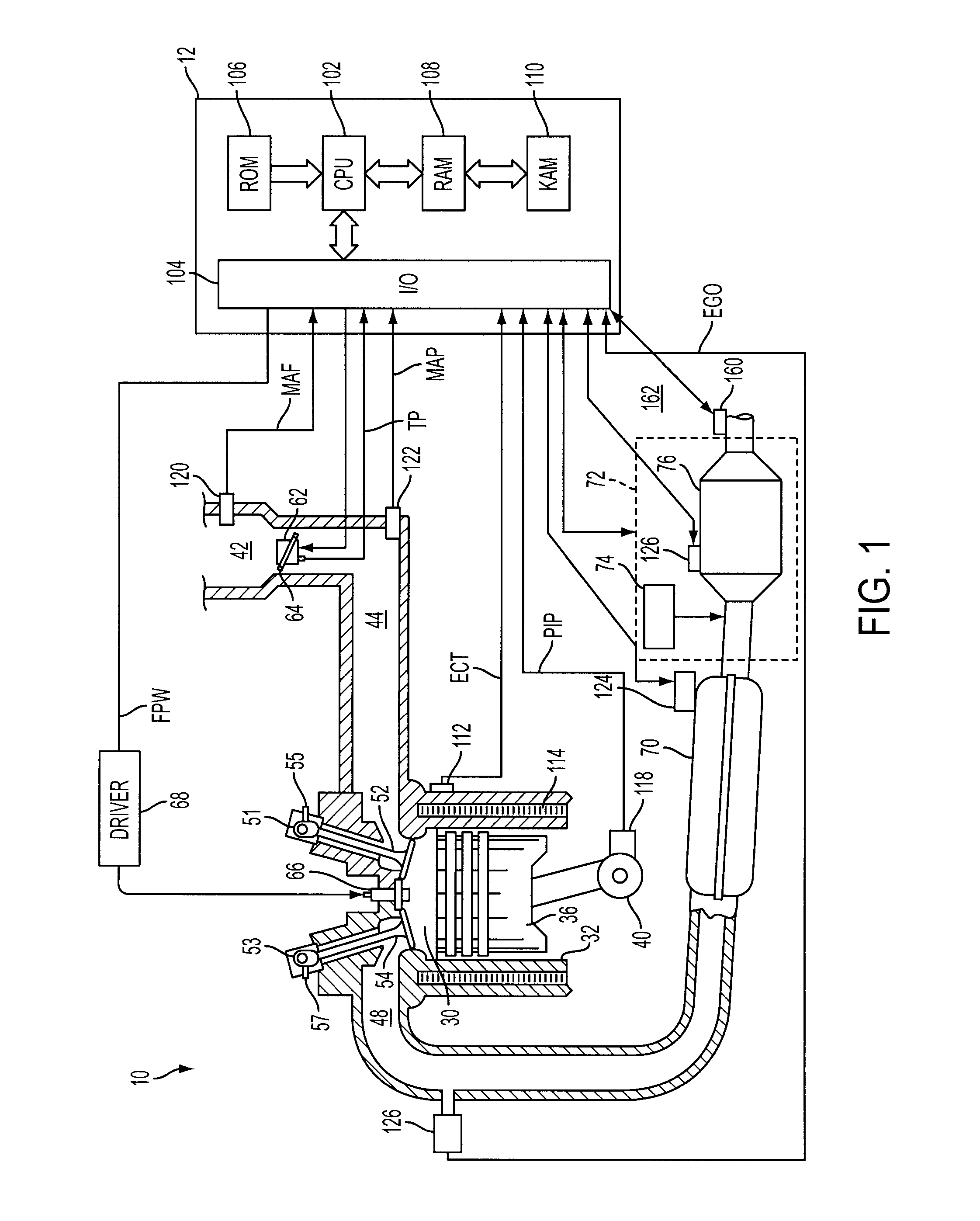
[0014]Referring to FIG. 1, direct injection internal combustion engine 10, comprising a plurality of combustion chambers and controlled by electronic engine controller 12, is shown. Combustion chamber 30 of engine 10 includes combustion chamber walls 32 with piston 36 positioned therein and connected to crankshaft 40. In one example, piston 36 includes a recess or bowl (not shown) to form selected levels of stratification or homogenization of charges of air and fuel. Alternatively, a flat piston may also be used.

[0015]Combustion chamber 30 is shown communicating with intake manifold 44 and exhaust manifold 48 via intake valve 52, and exhaust valve 54. Fuel injector 66 is shown directly coupled to combustion chamber 30 for delivering liquid fuel directly therein in proportion to the pulse width of signal fpw received from controller 12 via conventional electronic driver 68. Fuel is delivered to fuel system (not shown) including a fuel tank, fuel pumps, and a fuel rail. In some embodi...


PUM

PropertyMeasurementUnit
Temperatureaaaaaaaaaa

Abstract

A method of operating an internal combustion engine having a reductant delivery and storage system in an emission control system is disclosed. The method includes an approach for reducing thermal damage to aftertreatment devices in an exhaust system by reducing excessive exhaust gas temperatures created during particulate filter regeneration.

Description

TECHNICAL FIELD[0001]The present application relates to the field of automotive emission control systems, particularly to regulation of temperature in emission control systems.BACKGROUND AND SUMMARY[0002]Various approaches may be used for reducing soot in engine exhausts, including soot filters. One type of soot filter is a diesel particulate filter (DPF). A DPF is a device designed to remove diesel particulate matter from the exhaust gas of a diesel engine. However, collection of particulate matter on the DPF increases back pressure in the exhaust system, decreasing fuel economy. Therefore, the filter may be periodically cleaned or regenerated so that it may continue to be used. Regeneration burns off the accumulated particulate matter either passively, in DPFs that are constructed with a catalyst, or actively, by increasing exhaust temperature to further combust the soot. Exhaust temperature may be increased through engine management, a fuel burner, a catalytic oxidizer, resistive...

Claims


Application Information

Patent Timeline
IPC IPC(8): F01N3/035F01N3/20
CPCF01N2560/06F01N13/009F01N2610/02F01N2610/146F01N2900/0408F01N2900/1402F01N2900/1622F01N3/029F01N3/035F01N3/208F01N9/002Y02T10/47Y02T10/24F01N13/0093F01N2560/14Y02A50/20Y02T10/12Y02T10/40B01D46/46F01N3/023
Inventor RUONA, WILLIAM CHARLES
Owner FORD GLOBAL TECH LLC
Learn More