Eureka AIR delivers breakthrough ideas for toughest innovation challenges, trusted by R&D personnel around the world.

Toggle bolt assembly

a technology of toggle bolts and bolt assemblies, which is applied in the direction of fastening means, snap-action fasteners, dowels, etc., can solve the problems of difficulty in sequence, machine screw and mating nut pre-assembling, and weak design of prior art toggle bolts

Inactive Publication Date: 2009-04-23
FUCITO DOMINICK JOSEPH
View PDF0 Cites 27 Cited by
  • Summary
  • Abstract
  • Description
  • Claims
  • Application Information

AI Technical Summary

Benefits of technology

[0016]The object of the present invention is to provide an improved toggle bolt design, with the following advantages over the prior art:
[0017]The present invention incorporates an internally threaded sleeve in lieu of the prior art nut, and also incorporates a centering collar. When installed, the internally threaded sleeve, which is positioned on the inside surface of the wall skin, is engaged with a hole in the centering collar, which is positioned on the outside of the wall. These components are sized to provide a tight fit to the wall and to each other, such that they will remain in a fixed position on the wall without engagement of the screw.
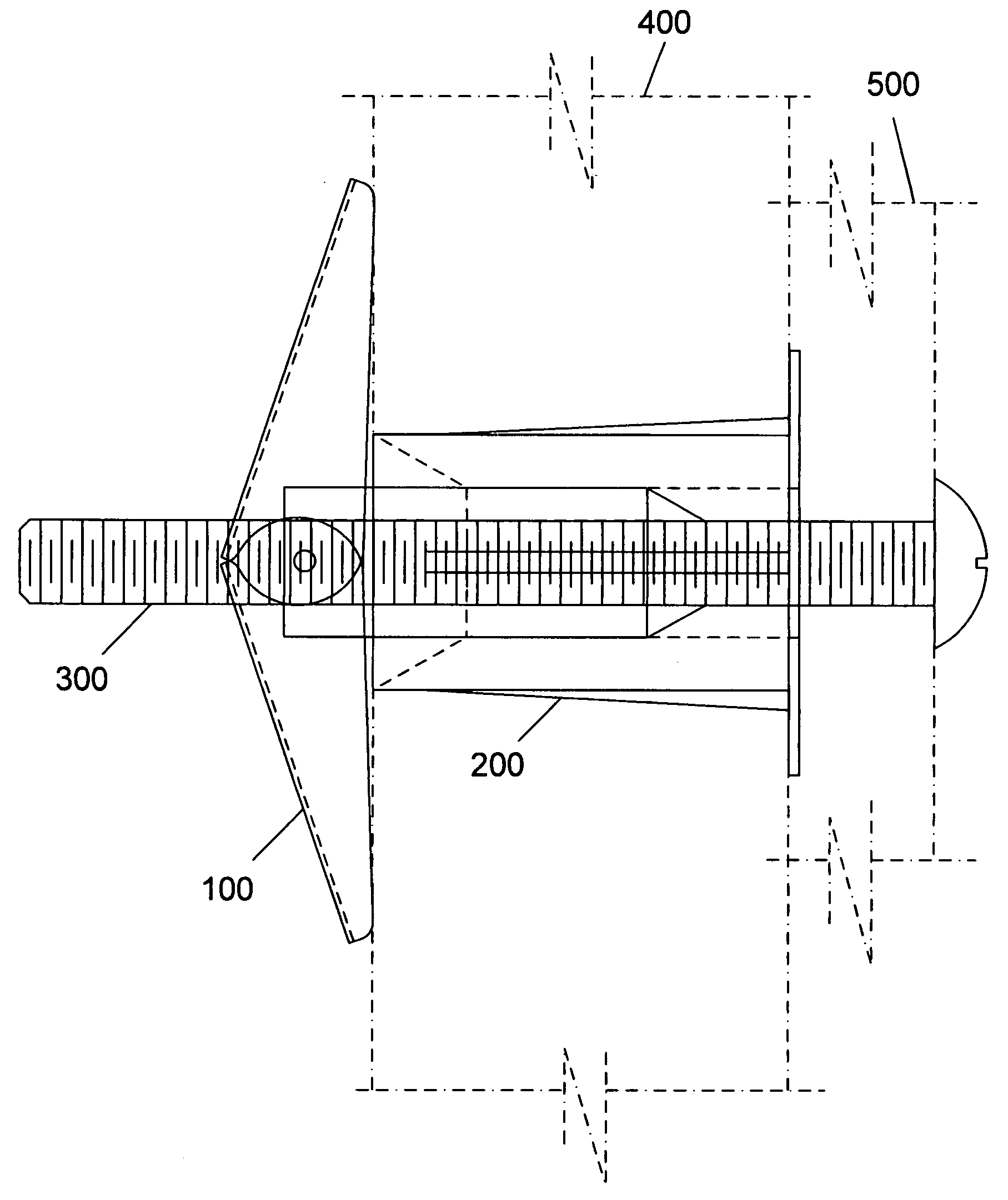
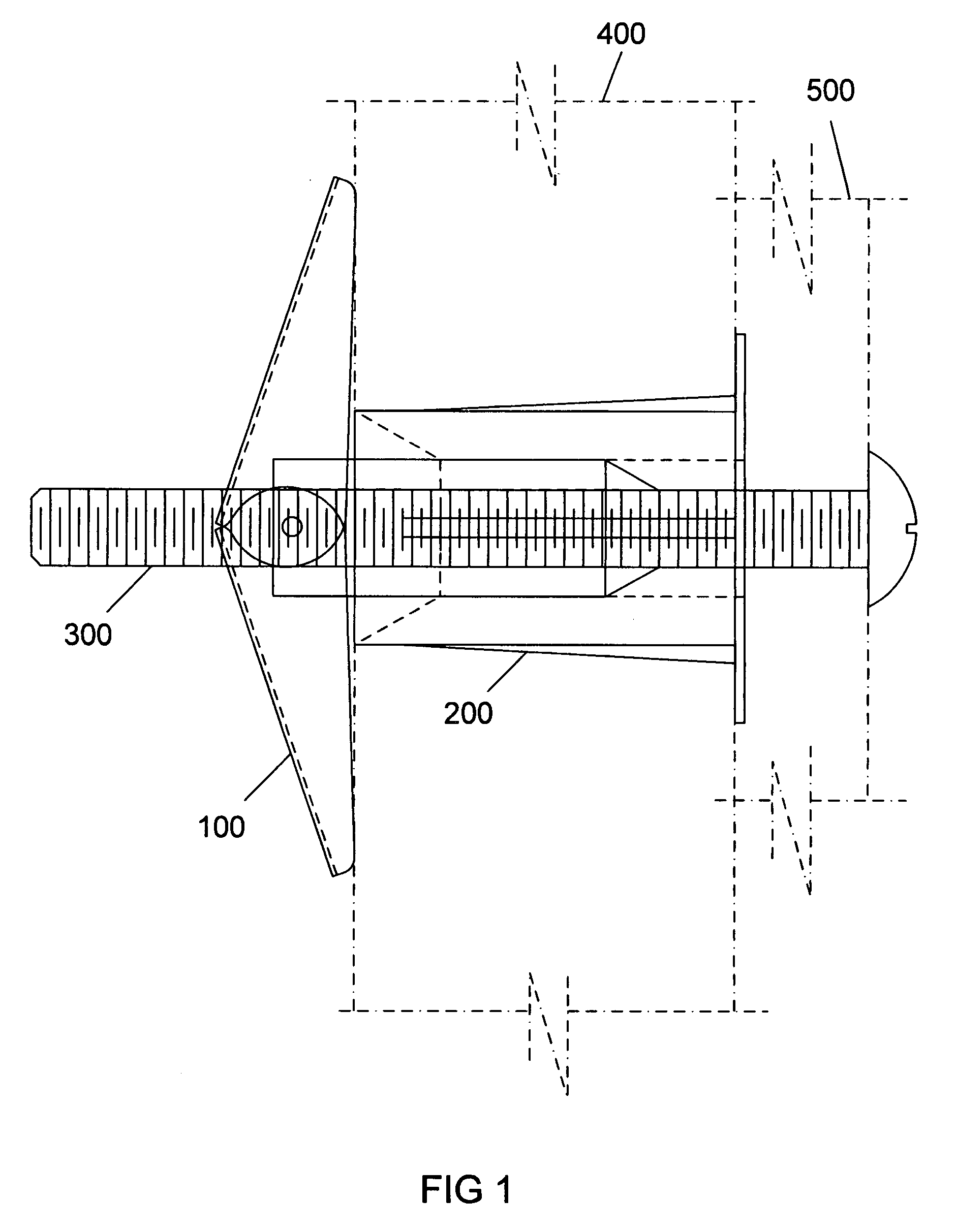
[0018]FIG. 1 is a side view of the preferred embodiment consisting of a toggle nut, collar, and screw, securing an object (shown in phantom) to a supportive structure (also shown in phantom).
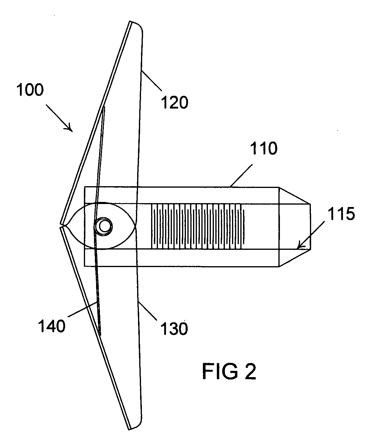
[0019]FIG. 2 is a side view of the toggle nut component of the preferred embodiment, shown in an expanded position.
[0020]FIG. 3 is a side view of the toggle nut component of the preferred embodiment, shown in a compressed position.
[0021]FIG. 4 is a sectional view of the toggle nut component of the preferred embodiment in its compressed position, taken along line 4-4 in FIG. 3.

Problems solved by technology

Despite its superior strength however, there are a number of weaknesses in the design of prior art toggle bolts.
One significant drawback is the requirement that the machine screw and mating nut be pre-assembled to the object to be secured.
This sequence becomes difficult when multiple toggle bolts are required to secure a large object.
However, this requires drilling oversized holes in the cabinet which could be detrimental to its structure.
It would also require the use of additional washers, and would result in a sloppy installation.
A second weakness in the design of prior art toggle bolts is the requirement that tension be applied to the screw when it is being tightened.
This becomes a problem as the head of the screw is drawn close to the object to be secured since it becomes difficult to grasp the screw to apply the necessary tension.
A third weakness in the design of prior art toggle bolts is the size of the hole which must be created in the wall relative to the size of the screw.
As a result, the secured object can, over time, slip downward due to gravity until the screw contacts the bottom of the hole.
A number of prior art toggle bolt designs have sought to alleviate the weaknesses identified above, with limited success.
For example, the designs disclosed in U.S. Pat. Nos. 6,203,260, RE 35,358, and 5,209,621 provide centering devices which prevent the secured objects from slipping downward over time, but do not include means to hold the nut in place without the screw, and do not provide means to prevent rotation of the nut without applying tension to the screw.
a) The toggle bolt assembly is rendered useless if the locking collar is accidentally engaged prior to installation in the wall;
b) installation involves the additional step of cutting off the excess plastic legs with wire cutter or other suitable tool;
c) once installed in the wall, the device is difficult to remove;
d) once installed, further tightening of the assembly is difficult, since this would require that both leg stubs which have been cut substantially flush with the locking collar be grasped and pulled outward while simultaneously pushing in the locking collar;
e) the device is relatively expensive to manufacture, retailing for approximately four times the cost of a conventional toggle bolt of the same size.
Similarly, the design disclosed in U.S. Pat. No. 4,822,226 does not provide an effective means to hold the nut in place behind the wall.
Although the nut would be retained by the assembly if the screw were to be removed, re-engagement of the screw with the nut would be difficult since the nut would not be visible to allow proper alignment with the screw, and the screw would have a tendency to push the nut along the retainer until it contacts the tipping finger, causing the toggle nut to tip and thereby further hindering the effort to properly align and engage the nut and screw.
The design disclosed in U.S. Pat. No. 3,389,631 will not effectively hold the toggle nut in place behind the wall.
Barbs pushed into a centering plug composed of cork, rubber, Styrofoam and other similar materials do not provide a dependable means to secure the nut.
In addition, dimensional constraints require that the barbs be adjacent to the inner bore of the plug and this proximity reduces the holding capability of the plug.

Method used


Image

  • Toggle bolt assembly
  • Toggle bolt assembly
  • Toggle bolt assembly

Examples


embodiment

Preferred Embodiment

[0041]The preferred embodiment of the present invention is illustrated in FIGS. 1 through 9. As illustrated in FIG. 1, the present invention is composed of three separate elements: a toggle nut 100, a collar 200, and a screw 300.

[0042]The toggle nut 100 is illustrated in FIGS. 2, 3 and 4. It is composed of a cylindrical sleeve 110, a first wing member 120, a second wing member 130, and a spring 140. As illustrated in FIG. 4, the cylindrical sleeve 110 has a substantially round outer surface 111 with a plurality of regularly spaced saw tooth shaped grooves 112. As illustrated in FIGS. 3 and 4, the outer surface 111 also includes two pins 113 diametrically opposed to each other and located near an end 114 of the sleeve 110. An inner surface 115 of the sleeve 110 has internal threads 116.

[0043]As illustrated in FIGS. 3 and 4, the first wing member 120 is of a substantially tapered channel cross section, with a first flange 121, a second flange 122, a web 123, a firs...


PUM


Abstract

An improved toggle bolt assembly consisting of a toggle nut 100, collar 200, and screw 300, wherein the toggle nut 100 consists of an internally threaded cylindrical sleeve 110, a first winged member 120, and a second winged member 130. The cylindrical sleeve 110 of the toggle nut 100 engages with a collar 200, acting to center the assembly, hold the toggle nut 100 and collar 200 in place without engagement of the screw 300, and eliminate the need to apply tension to the screw 300 during installation.

Description

CROSS-REFERENCE TO RELATED APPLICATIONS[0001]Not ApplicableSTATEMENT REGARDING FEDERALLY SPONSORED RESEARCH OR DEVELOPMENT[0002]Not Applicable[0003]REFERENCE TO SEQUENCE LISTING, A TABLE, OR A COMPUTER PROGRAM LISTING COMPACT DISC APPENDIX[0004]Not ApplicableBACKGROUND OF THE INVENTION[0005]1. Field of Invention[0006]This invention generally relates to an improved anchor, specifically the type of anchor commonly referred to as a toggle bolt.[0007]2. Prior Art[0008]Toggle bolts are used to secure objects to supportive structures such as walls. An example of a prior art toggle bolt design is disclosed in U.S. Pat. No. 7,226,261. It consists of a machine screw and a mating nut with two diametrically opposed pins which engage two wing members. These wing members rotate into a compressed orientation to allow insertion of the assembly into a hole in the supportive structure. Once positioned in the hole, the wings spring open and are brought into bearing against the surface of the supporti...

Claims


Application Information

Patent Timeline
Patent Type & Authority Applications(United States)
IPC IPC(8): F16B21/07
CPCF16B13/0808
Inventor FUCITO, DOMINICK JOSEPH
Owner FUCITO DOMINICK JOSEPH
Why Eureka
Eureka Blog
Learn More