
Low intermediate frequency receiver

a receiver and low intermediate frequency technology, applied in the field of communication systems, can solve the problems of limiting the extent to which such receivers can be used in modern communication systems, reducing the component count, and limiting the footprint and cost of the chips

Inactive Publication Date: 2009-04-23
INTEL CORP
View PDF13 Cites 7 Cited by
  • Summary
  • Abstract
  • Description
  • Claims
  • Application Information

AI Technical Summary

Benefits of technology

[0008]The following presents a simplified summary of the invention in order to provide a basic understanding of some aspects of the invention. This summary is not an extensive overview of the invention, and is neither intended to identify key or cr

Problems solved by technology

This typically reduces the component count, and may correspondingly limit the footprint and cost of the chipset.
While zero-IF receivers offer a more compact chipset, technical barriers often limit the extent to which such receivers can be used in modern communication systems.
For example, because a local oscillator signal (LO) in these receivers is the same as the RF frequency, the LO signal may leak from the receiver to the antenna, which can cause interference with other receivers on the same frequency-band.
Also, DC offset, which comes from the self-mixing of LO leakage, may seriously deteriorate the SNR (Signal Noise Ratio).
Due to the fact that these separate stages are relatively area intensive, conventional low-IF receivers have a relatively large footprint.

Method used


Image

  • Low intermediate frequency receiver
  • Low intermediate frequency receiver
  • Low intermediate frequency receiver

Examples


Embodiment Construction

[0015]The present invention will now be described with respect to the accompanying drawings in which like numbered elements represent like parts. The figures and the accompanying description of the figures are provided for illustrative purposes and do not limit the scope of the claims in any way.

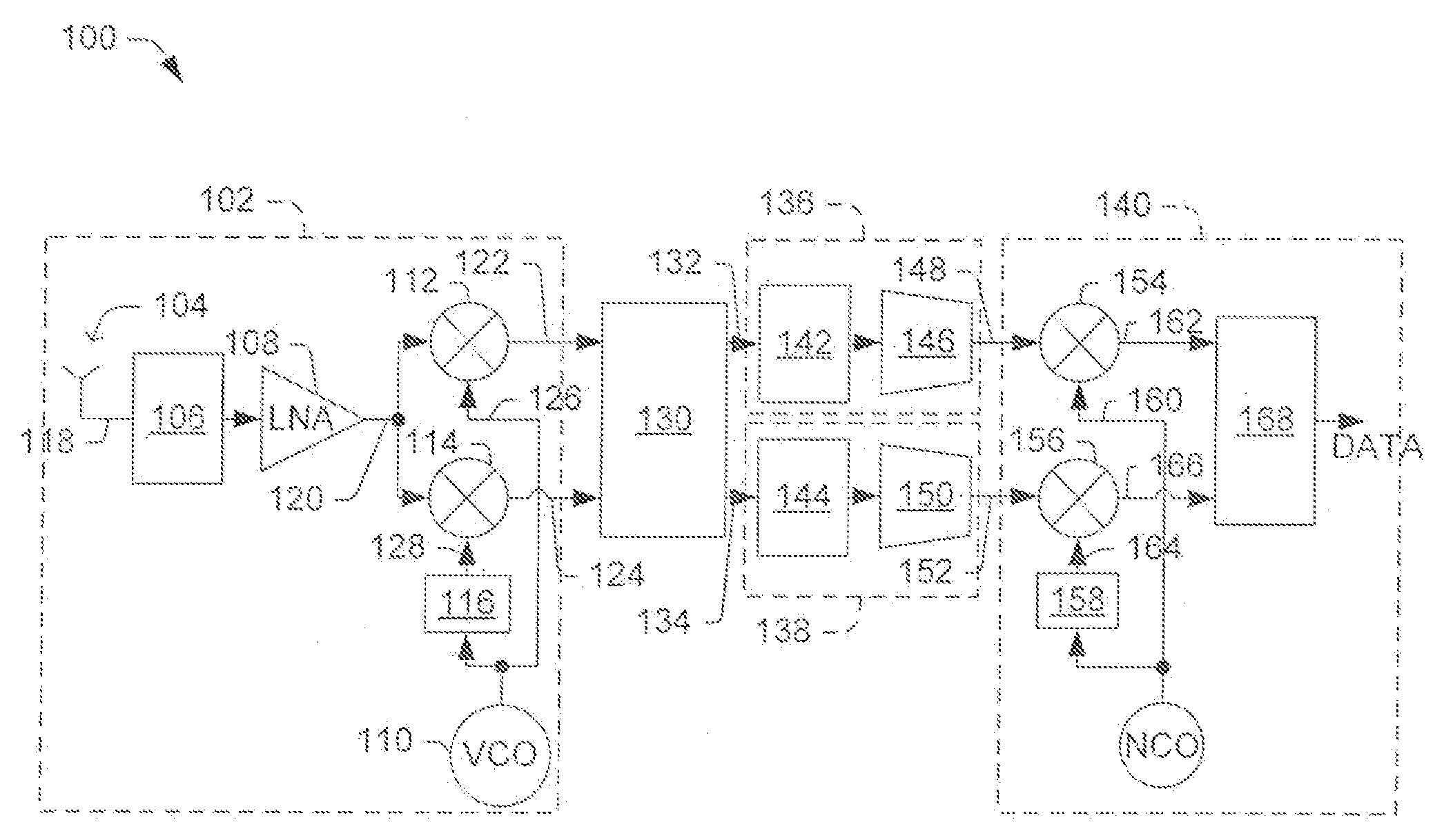
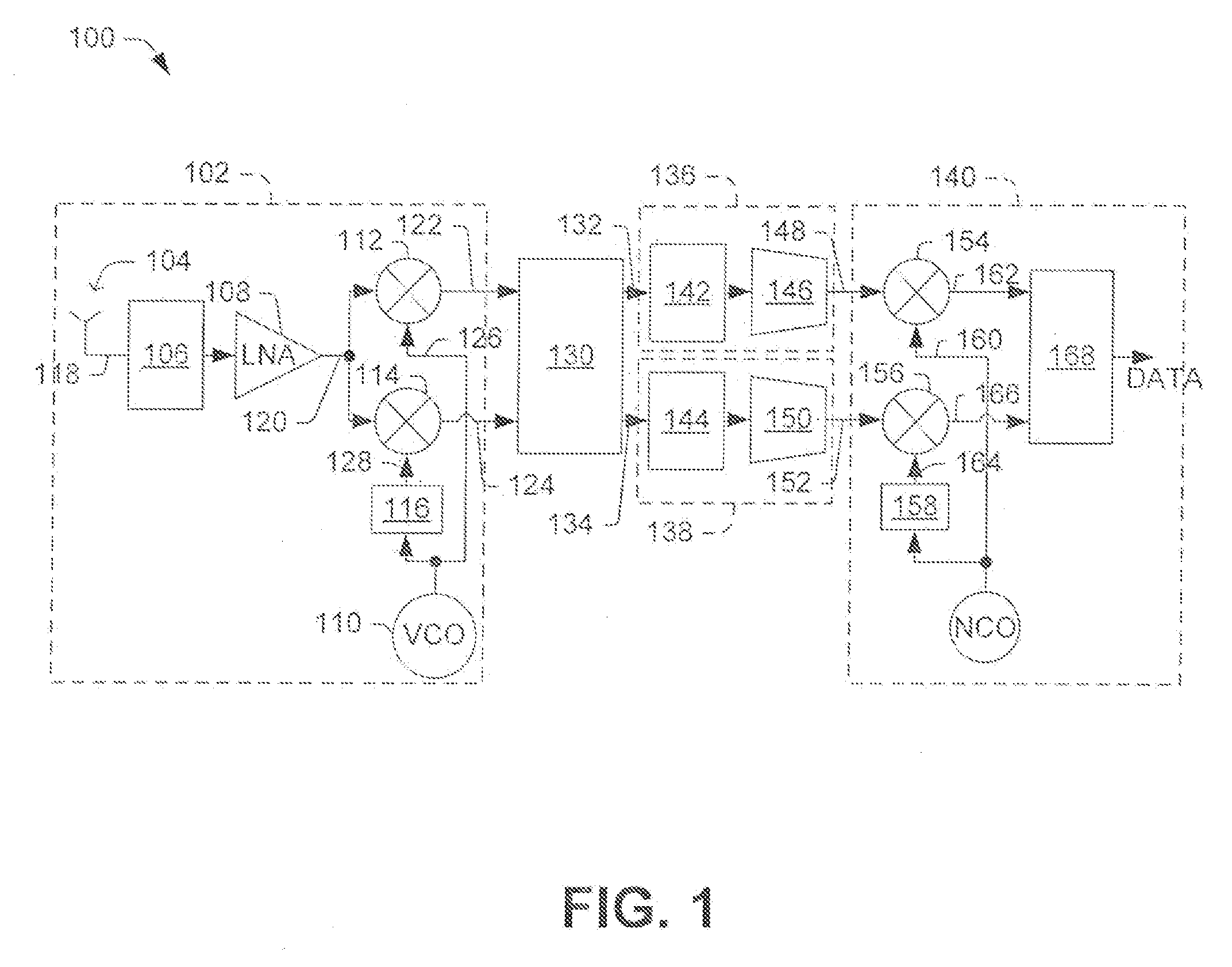
[0016]Referring to FIG. 1, one can see one embodiment of a low-intermediate frequency (low-IF) receiver 100. The low-IF receiver 100 includes an analog front end 102 with an I / Q demodulator structure. This analog front end 102 includes the following components: an antenna 104, a matching network 106, low-noise amplifier (LNA) 108, a voltage controlled generator (VCO) 110, two mixers (112, 114), and a 90° phase shift module 116.

[0017]During operation, the LNA 108 passes modulated IQ data received from the antenna 104 to the first and second mixers 112, 114, respectively. In essence, the first and second mixers 112, 114, respectively, perform signal multiplication and either up-convert or down...


PUM


Abstract

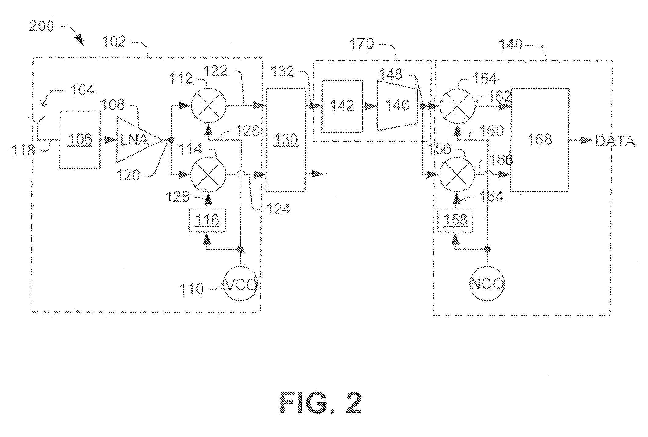
One embodiment relates to a low intermediate frequency (IF) receiver. The low-IF receiver includes an analog front end that is configured to receive a modulated IQ data signal and provide an in-phase signal and a quadrature signal, where the in-phase signal is phase shifted by approximately 90° relative to the quadrature signal. The low-IF receiver further includes a digital processing block, and a single path that provides only one of the in-phase signal and the quadrature signal to the digital processing block. Other receivers and methods are also disclosed.

Description

FIELD OF THE INVENTION[0001]The present invention relates generally to communication systems, and more specifically to receivers used within these communication systems.BACKGROUND[0002]Several trends presently exist with regards to wireless communication devices. For example, in comparison to previous generations of wireless devices, modern wireless devices are more compact, more affordable, and have longer battery lifetimes. While consumers may largely take these trends for granted, these trends are the result of significant engineering efforts.[0003]To communicate with other devices, many wireless devices include receivers. These receivers are typically included in chip sets that enable wireless communication via one of several communication standards, such as Bluetooth, Digital Enhanced Cordless Telecommunication (DECT), and numerous others. Because these chip sets are used commonly in cell phones, music players, personal digital assistants (PDAs), etc., it is desirable for the c...

Claims


Application Information

Patent Timeline
IPC IPC(8): H04L25/10H03D1/00H04L27/06
CPCH04B1/30H04L27/3881H04L27/3845H04L27/38
Inventor VAN WAASEN, STEFANGREWING, CHRISTIANLEWIS, MICHAEL
Owner INTEL CORP
Learn More