Ion beam extraction assembly in an ion implanter

a technology of ion beam and assembly, which is applied in the direction of ion beam tubes, instruments, nuclear engineering, etc., can solve the problems of high cost and heavy arrangement, and achieve the effect of less cost and significant weight and cost savings

Inactive Publication Date: 2009-04-23
APPLIED MATERIALS INC
View PDF11 Cites 12 Cited by
  • Summary
  • Abstract
  • Description
  • Claims
  • Application Information

AI Technical Summary

Benefits of technology

[0016]Advantageously, the present invention provides a combination of tungsten and other parts, such as graphite parts. Tungsten is used for parts of the electrode that are prone to beam strike, while graphite or another material is used for parts of the support that are far less prone to beam strike. Thus the benefit of a tungsten electrode is realised, but in an arrangement that may have significant weight and cost savings over an all tungsten arrangement. Thus, the different material should be less expensive than tungsten and / or lighter.

Problems solved by technology

However, such an arrangement would be very heavy, and also very expensive.

Method used


Image

  • Ion beam extraction assembly in an ion implanter
  • Ion beam extraction assembly in an ion implanter
  • Ion beam extraction assembly in an ion implanter

Examples


Embodiment Construction

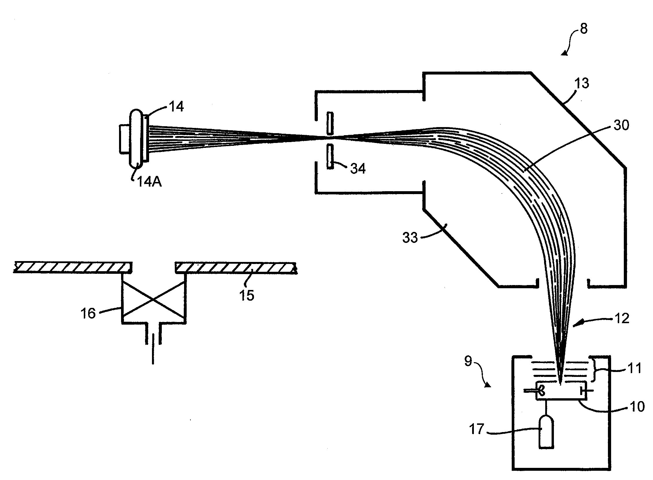
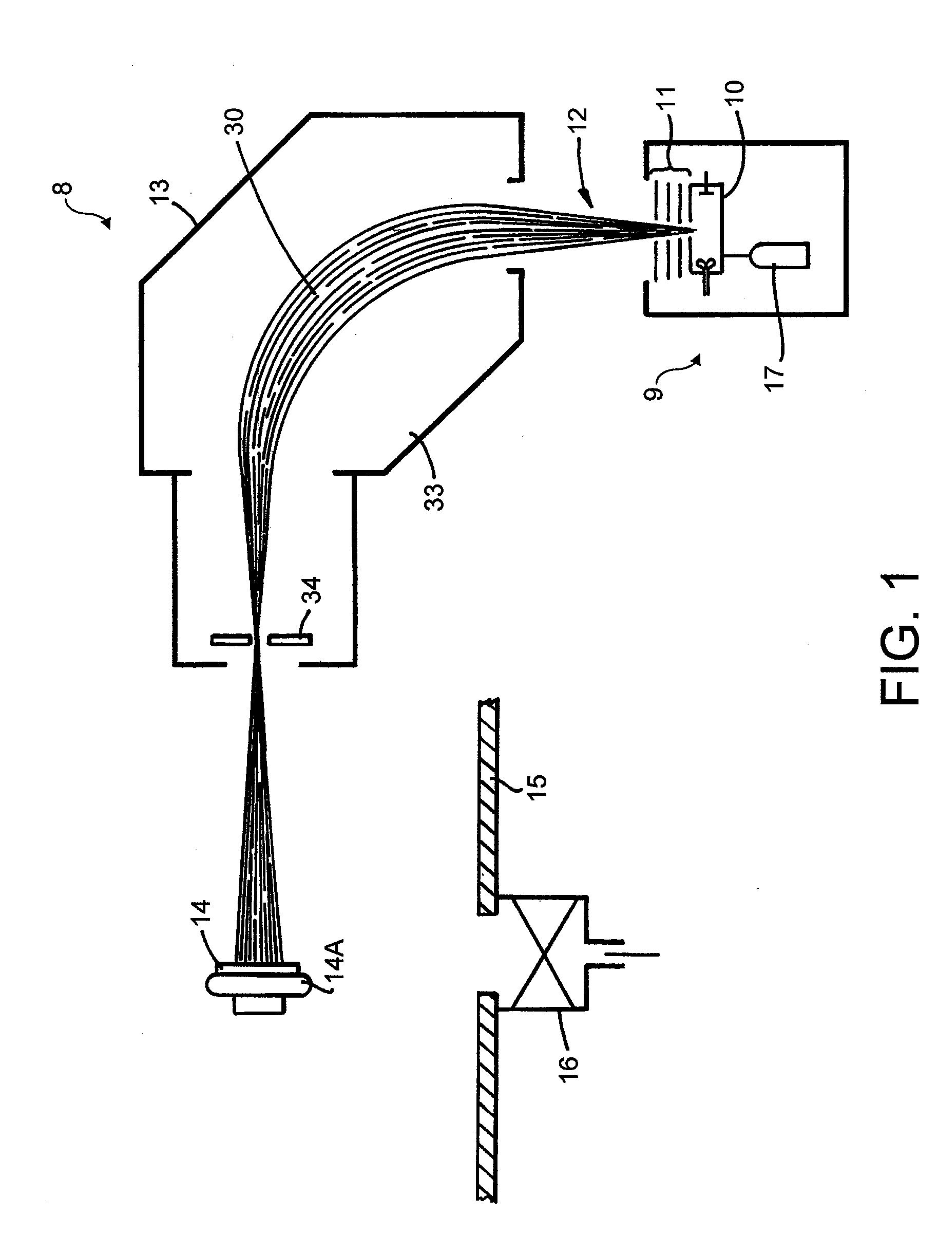
[0042]Referring to FIG. 1, a conventional ion implanter is shown schematically at 8. The ion implanter 8 includes ion beam generation apparatus 9. The ion beam generation apparatus 9 comprises an ion source 10 with an extraction assembly 11. The extraction assembly 11 extracts and directs an ion beam 12 through an ion mass selector 13 to impinge on a wafer 14 mounted on a wafer holder 14A. As is well known to workers in this field, the above elements of the ion implanter 8 are housed in a vacuum housing of which a part 15 only is illustrated in FIG. 1. The vacuum housing may be evacuated by a vacuum pump 16.

[0043]The ion source 10 may comprise any known ion source such as a Freeman source, a Bernas source or an indirectly heated cathode source. The ion source 10 comprises an arc chamber which is fed a supply of a feed gas containing a desired dopant, ions of which are to be implanted in the wafer 14. The feed gas may be supplied to the arc chamber in gaseous or vapour form, e.g. fro...


PUM


Abstract

The present invention relates to an ion beam extraction assembly for use in an ion beam generation apparatus such as those used, for example, in an ion implanter. An ion beam extraction assembly is provided for mounting within an ion beam generating apparatus comprising an ion source such that the extraction assembly is operable to extract ions from the ion source as an ion beam. The extraction assembly comprises an electrode assembly separate from the ion source, an electrode of the electrode assembly defining at least partly a path through the extraction assembly for passage of an ion beam. At least a part of the electrode assembly adjacent the path is tungsten and at least a part of the electrode assembly that is remote from the path is formed from a less expensive and/or lighter material.

Description

FIELD OF THE INVENTION[0001]The present invention relates to an ion beam extraction assembly for use in an ion beam generation apparatus such as those used, for example, in an ion implanter.BACKGROUND OF THE INVENTION[0002]Ion implantation techniques, e.g. for modifying the electrical conductivity properties of semiconductor materials, are known in the manufacture of integrated circuit structures in semiconductor wafers. Such ion implanters generally comprise an ion beam generation apparatus having a source of ions of the element to be implanted in the semiconductor wafer, and an extraction assembly for extracting ions from the source and forming a beam of the extracted ions. The ion beam so produced is then passed through a mass analyser and selector for selecting a particular species of ions in the ion beam for onward transmission for implantation in the wafer or target substrate.[0003]The extraction assembly may be a triode extraction assembly, so called because it involves an ar...

Claims


Application Information

Patent Timeline
Patent Type & Authority Applications(United States)
IPC IPC(8): H01J27/00
CPCH01J27/024H01J37/3171H01J37/08
Inventor SPRAGGON, LEEMURRELL, ADRIAN
Owner APPLIED MATERIALS INC
Why Eureka
Try Eureka