
System and method for sensing fuel moisturization

a fuel moisturization and sensing technology, applied in the field of monitoring and measuring fuel moisturization levels, can solve the problems of introducing a large error in the estimation of moisture content, the supply of moisturized fuel to a dln gas turbine combustion system requires extremely tight control of the fuel saturation process, and the depletion of plant performance, so as to achieve accurate measurement of on-line moisture content

Inactive Publication Date: 2009-04-23
GENERAL ELECTRIC CO
View PDF10 Cites 13 Cited by
  • Summary
  • Abstract
  • Description
  • Claims
  • Application Information

AI Technical Summary

Benefits of technology

[0008]Thus, it would be desirable to have a sensor that can accurately meas

Problems solved by technology

If fuel supply conditions deviate excessively from the designed fuel specifications, plant performance will degrade.
Moisturized fuel supply to a DLN gas turbine combustion system requires extremely tight control on the fuel saturation process in a moisturization column due to tight fuel specification tolerances, frequent load changes, and rapid load changes.
Because the fuel moisture in the moisturized stream is small in relation to the total flow, a small error in the total flow measurement may introduce a large error in the moisture content estimation.
Though accurate, the gas chromatography measurements are time consuming because the process involves sampling of the fuel gas and taking measurements at a reduced pressure and temperature.
Therefore, the information about the components at high pressures and temperatures is not obtainable.

Method used


Image

  • System and method for sensing fuel moisturization
  • System and method for sensing fuel moisturization
  • System and method for sensing fuel moisturization

Examples


example 1

[0061]The vessel was evacuated and filled with nitrogen up to a desired pressure. A data acquisition system acquiring the data from the moisturization sensor system was initiated and the transmitted and reference intensities were monitored. Steam was introduced in the vessel and the transmitted and reference intensities were monitored. FIG. 8 illustrates the variation of transmitted intensity through N2 at 55 psi (˜379 kPa) and steam at 10 psi (˜68 kPa).

[0062]The absorption feature of light at 945 nm in FIG. 8 shows that as the steam was introduced inside the chamber at point 189, there was a drop 190 in the transmitted intensity till a steady state was attained again at and beyond point 191. Line 192 marks the baseline intensity level.

[0063]The steam mass was measured at different steam and N2 pressures. The results were validated using thermodynamic table based calculations and pressure, volume, and temperature (P, V, T) based calculations. For thermodynamic table based calculatio...

example 2

[0065]The vessel was evacuated and filled with carbon dioxide up to a desired pressure. A data acquisition system acquiring the data from the moisturization sensor system was initiated and the transmitted and reference intensities were monitored. Steam was introduced in the vessel and the transmitted and reference intensities were continued to be monitored. FIG. 9 illustrates the variation of transmitted intensity through CO2 at 30 psi (˜207 kPa) and steam at 10 psi (˜68 kPa).

[0066]Line 202 marks the baseline intensity level. The absorption feature of light at 945 nm in FIG. 9 shows that as the steam was introduced inside the chamber at point 204, there was a drop 200 in the transmitted intensity till a steady state was attained again in the region 206. The DC shift due to absorption of 10 psi (68 kPa). steam in the steam+CO2 mixture is indicated in the FIG. 9. This DC shift in the absorption spectra is used to calculate the steam mass in the gas mixtures.

[0067]In one embodiment, th...


PUM


Abstract

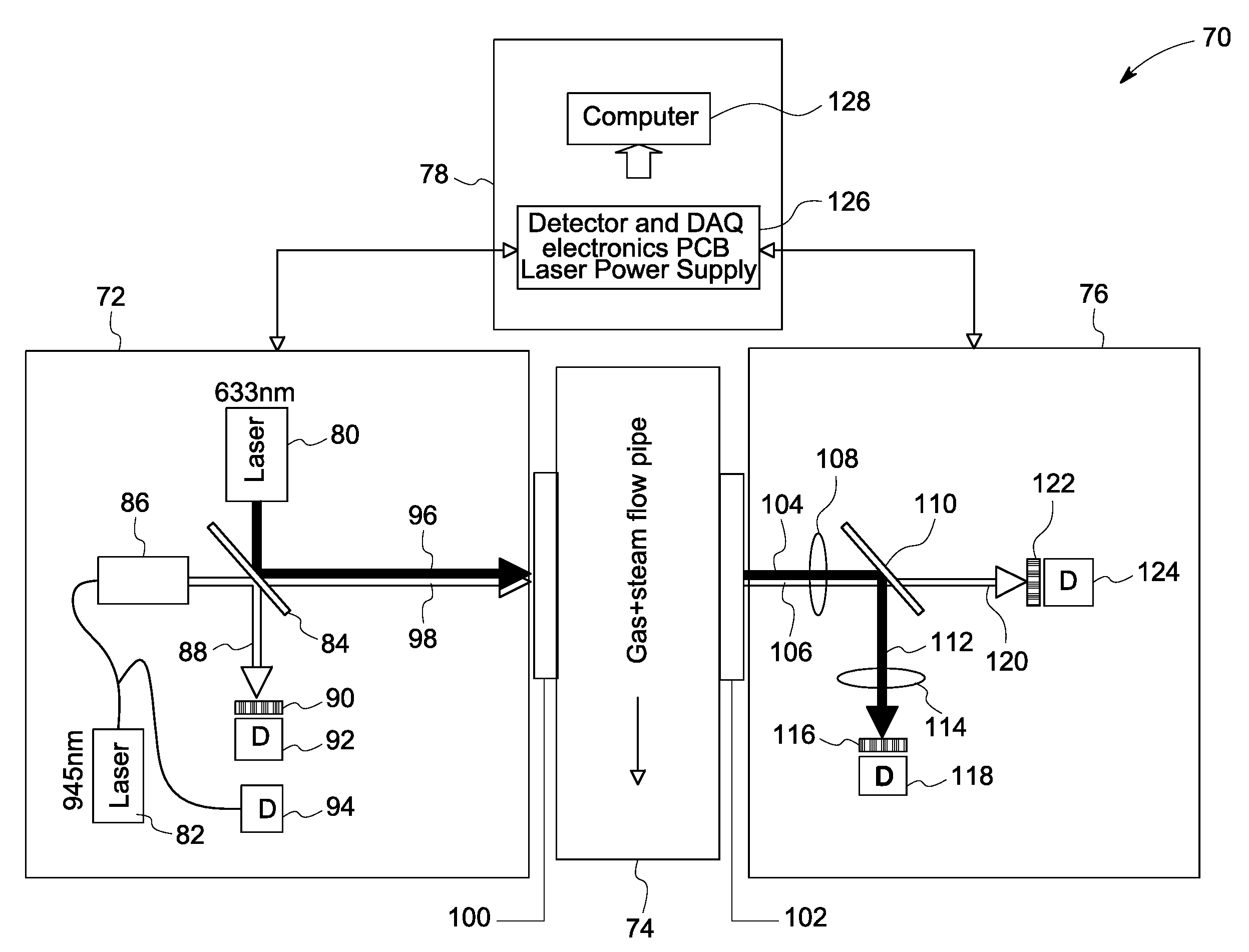
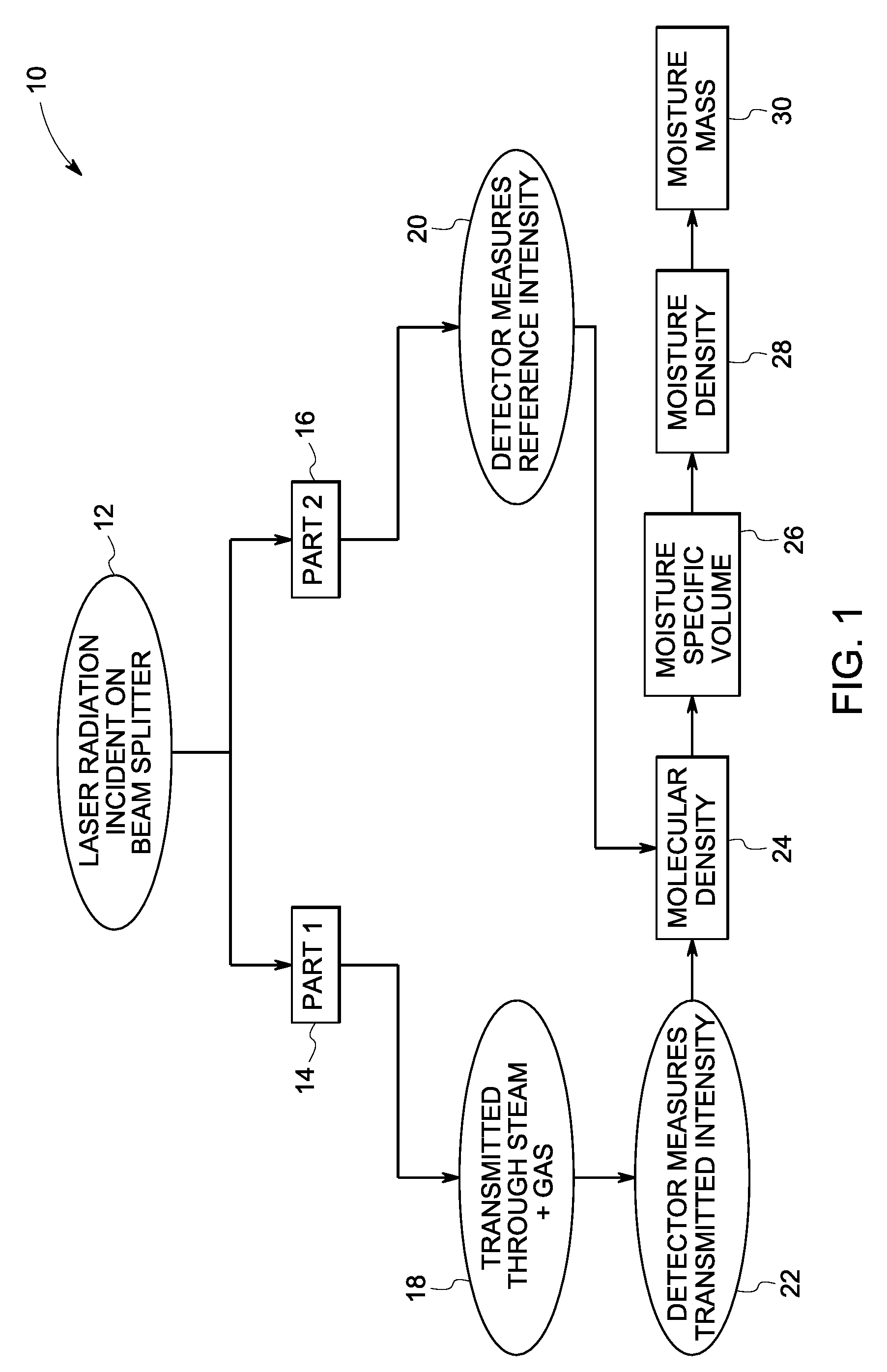
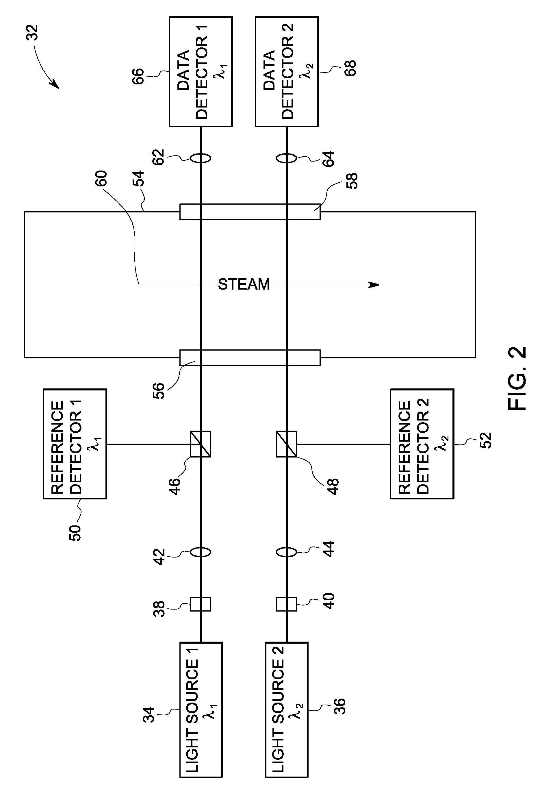
A fuel moisturization sensor system is disclosed. The fuel moisturization sensor system includes a first light source configured for emitting light through a fuel and moisture flow path at a first wavelength, wherein the first wavelength is at least partially absorbable by the moisture when in a vapor phase and substantially not absorbable by the fuel, and a second light source configured for emitting light through the fuel and moisture flow path at a second wavelength, wherein the second wavelength is preferentially scattered by moisture when in a liquid phase and substantially not absorbed by the fuel or by the moisture when in a vapor phase, a detector system configured to detect light transmitted through the flow path at the first and second wavelengths and to generate a first data signal corresponding to the transmission at the first wavelength and a second data signal corresponding to the transmission at the second wavelength.

Description

BACKGROUND[0001]The invention relates generally to monitoring and measuring fuel moisturization levels. The invention particularly relates to optical techniques for monitoring and measuring fuel moisturization levels.[0002]Fuel moisturization systems have been used in combined cycle power plants in an attempt to increase power output and thermodynamic efficiency. One example embodiment is described in commonly assigned U.S. Pat. No. 6,389,794. In such systems, natural gas is saturated with water, and the moisturized fuel is heated to saturation conditions at the design gas pressure. The increased gas mass flow due to the addition of moisture results in increased power output from gas and steam turbines.[0003]Natural gas fired combined cycle plants with Dry Low NOx (DLN) combustion systems impose strict requirements on the fuel gas saturation process due to tight fuel specification tolerances. These requirements relate to variables such as heating value, temperature, specific gravity...

Claims


Application Information

Patent Timeline
IPC IPC(8): G01J3/00G01N21/00
CPCG01N21/3151Y02E20/16G01N2021/3155G01N21/534
Inventor MITRA, CHAYANBANERJEE, AYANMAITY, SANDIPNORMAN, BRUCE GORDONBALL, JR., DAVID WESLEYJOHANSEN, AARRON DELL
Owner GENERAL ELECTRIC CO
Learn More