Microwave Field Director Structure Having V-Shaped Vane Doublets

Inactive Publication Date: 2009-04-16
EI DU PONT DE NEMOURS & CO
View PDF21 Cites 0 Cited by
  • Summary
  • Abstract
  • Description
  • Claims
  • Application Information

AI Technical Summary

Benefits of technology

[0032]In one embodiment the invention is directed to a field director structure in which the materials used to fabricate the vanes of the field director structure are selected with the view to making the field director structure sufficiently physically robust so as to be able to remain self-supporting over multiple uses. In addition, and perhaps more importantly, in most aspects of this embodiment of the field director structure the materials of construction are arranged in a laterally symmetric fashion across the thickness of each vane. Arranging materials in a laterally symmetric fashion across the thickness of each vane equalizes thermal expansion effects due to heating over repetitive exposures to microwave energy, thus reducing the tendency to warp and contributing to the re-usability of the field director structure. One of several forms of vane support structure can be used to enhance the physical robustness of the vane array.

Problems solved by technology

These hot and cold regions cause the food to warm or to cook unevenly.
If a microwave susceptor material is present the browning and crisping effect is similarly uneven.
However, the averaging effect produced by the turntable's rotation occurs along circumferential paths within the oven and not along radial paths.
Thus, even with the use of the turntable bands of uneven heating within the food are still created.
Owing to the number of hot regions encountered and cold regions avoided points J and L experience considerably more energy exposure than Point K. If the region of the food product in the vicinity of the path of point J is deemed fully cooked, then the region of the food product in the vicinity of the path of point L is likely to be overcooked or excessively browned (if a susceptor is present).
On the other hand the region of the food product in the vicinity of the path of point K is likely to be undercooked.
This problem is exacerbated when the field director is used with a susceptor.
The warping and discoloration render the field director unsightly and may be of sufficient severity to render the field director unsuitable for a second use.
Thus, the typical prior art field director is considered to be unsuitable for multiple uses.

Method used


Image

  • Microwave Field Director Structure Having V-Shaped Vane Doublets
  • Microwave Field Director Structure Having V-Shaped Vane Doublets
  • Microwave Field Director Structure Having V-Shaped Vane Doublets

Examples


Embodiment Construction

[0059]Throughout the following detailed description similar reference characters refers to similar elements in all figures of the drawings.

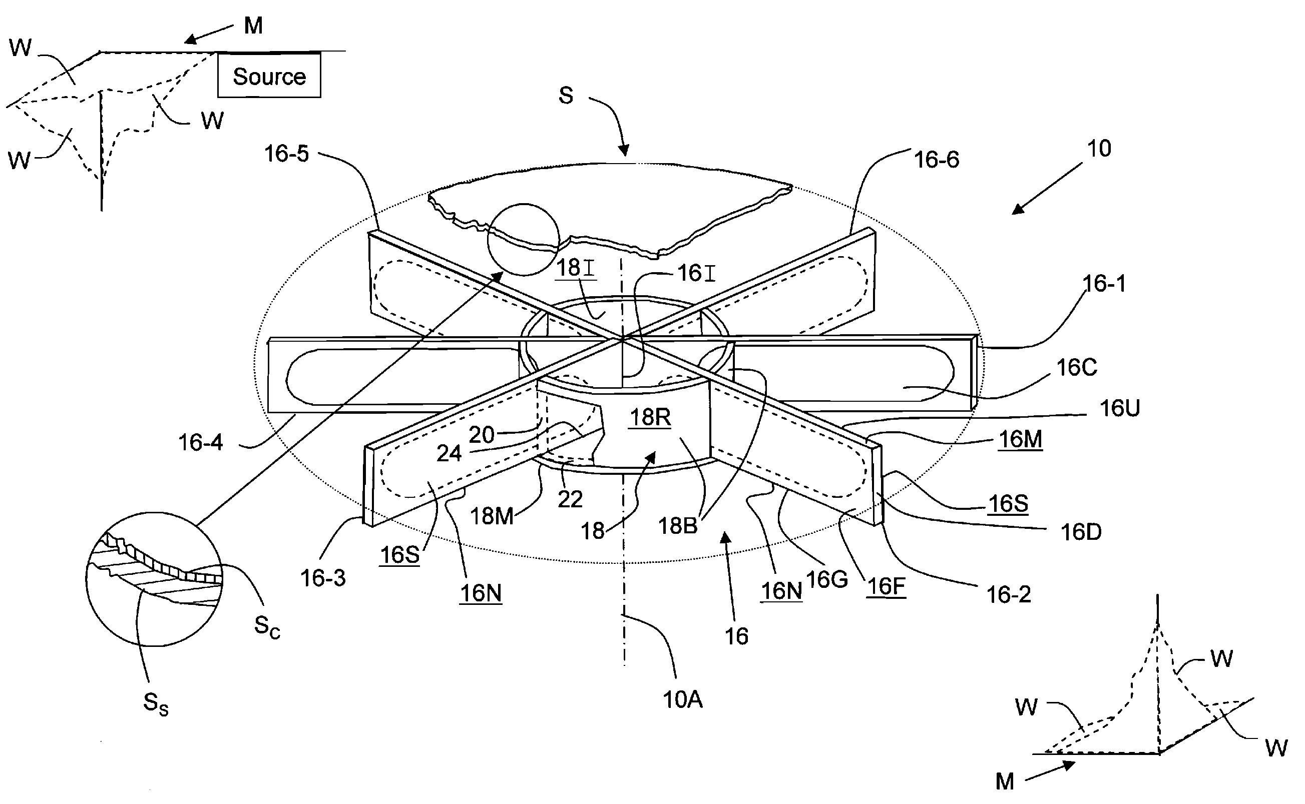
[0060]With reference to FIGS. 2A, 4A and 5A shown are pictorial views of alternative embodiments of a reusable self-supporting field director structure, generally indicated by the reference numeral 10, 10′ and 10″ respectively, each in accordance with the present invention. In each case the field director structure 10, 10′, 10″ has a respective reference axis 10A, 10′A and 10″A extending through its geometric center.

[0061]The field director structure 10, 10′, 10″ is, in use, disposed within the resonant cavity on the interior of a microwave oven M. The oven M is suggested only in outline form in FIGS. 2A, 4A and 5A. In operation, a source in the oven produces an electromagnetic wave having a predetermined wavelength. A typical microwave oven operates at a frequency of 2450 MHz, producing a wave having a wavelength on the order twelve centimeters ...


PUM


Abstract

A self-supporting field director structure for use in heating an article in a microwave oven is characterized by a vane array comprising a plurality of V-shaped vane doublets, wherein each vane doublet itself comprises a first and a second vane. Each vane extends radially outwardly from the central axis. Each vane has a substrate formed from an electrically non-conductive material, with a portion of each vane being electrically conductive. A vane support structure is attached to the vane array.

Description

FIELD OF THE INVENTION[0001]The present invention is directed to a reusable microwave field director assembly for use in a microwave oven.CROSS-REFERENCE TO RELATED APPLICATIONS[0002]Subject matter disclosed herein is disclosed in the following copending applications filed contemporaneously herewith and assigned to the assignee of the present invention:[0003]Molded Microwave Field Director Structure (CL-3655);[0004]Microwave Field Structure Having Vanes Covered With A Conductive Sheath (CL-4040);[0005]Microwave Field Director Structure Having Vanes With Outer Ends Wrapped With A Conductive Wrapper (CL-4055);[0006]Microwave Field Director Structure With Vanes Having A Conductive Material Thereon (CL-4060);[0007]Method of Making A Microwave Field Director Structure Having V-Shaped Vane Doublets (CL-4058);[0008]Microwave Field Director Structure With Laminated Vanes (CL-4037);[0009]Microwave Field Director Structure Having Over-Folded Vanes (CL-4064);[0010]Method of Making A Microwave ...

Claims


Application Information

Patent Timeline
IPC IPC(8): H05B6/80
CPCH05B6/72
Inventor CORCORAN, JR., WILLIAM R.
Owner EI DU PONT DE NEMOURS & CO
Why Eureka
Try Eureka