
Open-hole wellbore lining

a wellbore and wellbore technology, applied in the direction of wellbore/well accessories, sealing/packing, coatings, etc., can solve the problems of damage to the wellbore, negative economic impact, softening and disintegration of the wellbore wall,

Inactive Publication Date: 2009-04-09
SCHLUMBERGER TECH CORP
View PDF15 Cites 59 Cited by
  • Summary
  • Abstract
  • Description
  • Claims
  • Application Information

AI Technical Summary

Benefits of technology

[0014]By providing the actinic radiation for solidifying or gelling the fluid composition in situ in the wellbore proximate to the region in which the solidified or gelled fluid composition is desired, more control over the lining of the wellbore is achievable. Thus, in accordance with an embodiment of the present invention, specific regions of a wellbore, e.g. cracked or fissured regions, can be lined or re-lined. Advantageously, the present invention also allows a wellbore, such as an open-hole wellbore, to be lined without the need to halt the drilling, or with the need to complete the drilling before lining the wellbore.
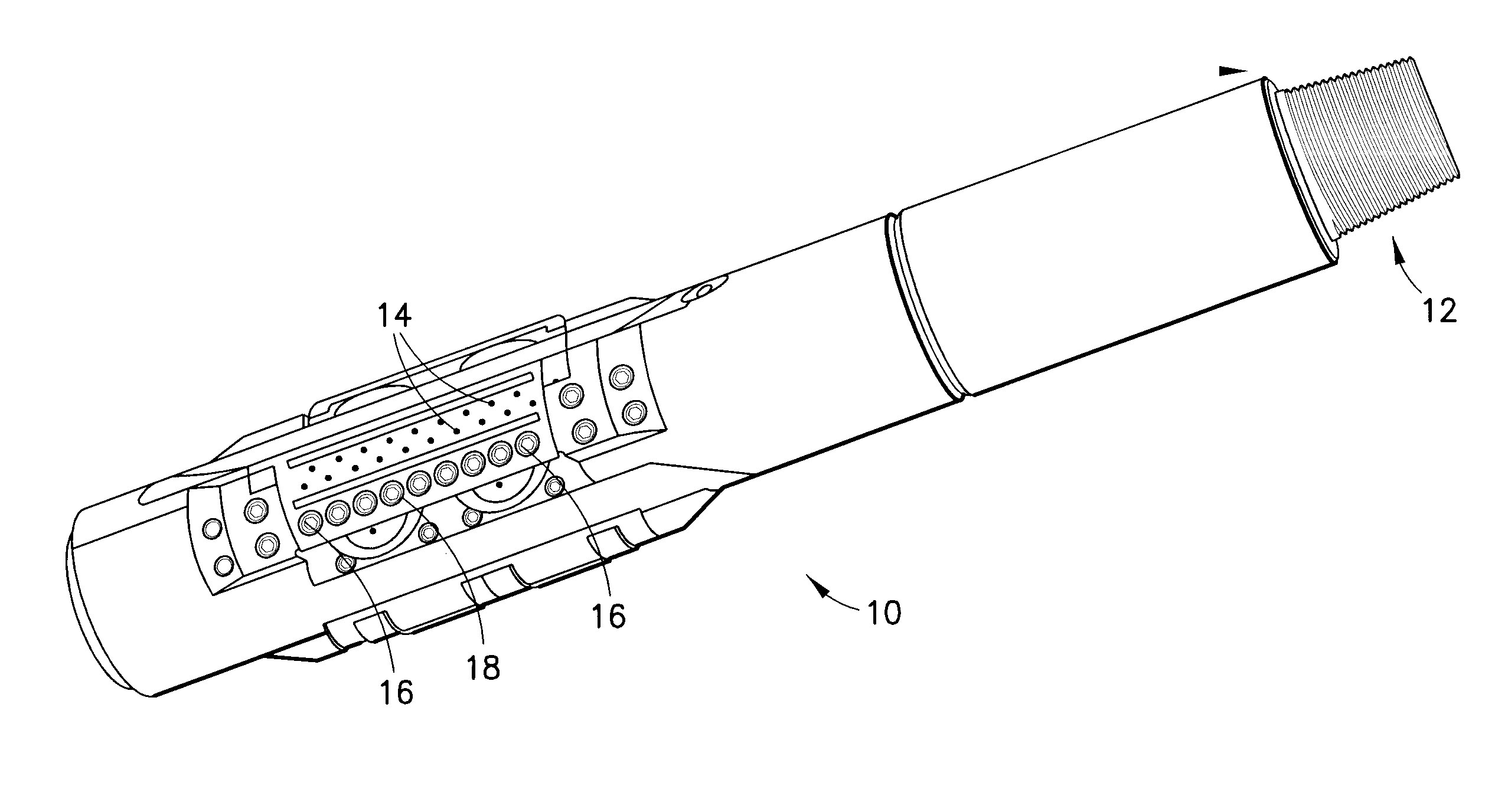
[0025]A tool according to the present invention could be an element of a drill string stabiliser. Advantageously, drill string stabilisers are generally in contact with a portion of the wellbore wall, and so a tool according to the present invention which is an element of such a stabiliser should also be located close to the wellbore wall, thereby allowing the wellbore to be lined progressively as the drill string is lowered downhole.

Problems solved by technology

Such relatively high pressure can produce undesirable mechanical forces on the formation, which may lead to wellbore damage.
This has disadvantages in that it delays the extraction of valuable oil and / or gas from the well and consequently has a negative economic impact.
The interaction of water with a shale and / or clay wellbore wall can cause the shale and / or clay to swell, thereby contracting the wellbore and possibly leading to softening and disintegration of the wall of the wellbore.
However, the use of such a process has its disadvantages.
The graft polymer is relatively indiscriminate, and it is therefore likely to be difficult to control accurately the thickness or location of the layer which it forms on the wall of the wellbore.

Method used


Image

  • Open-hole wellbore lining
  • Open-hole wellbore lining
  • Open-hole wellbore lining

Examples


example 1

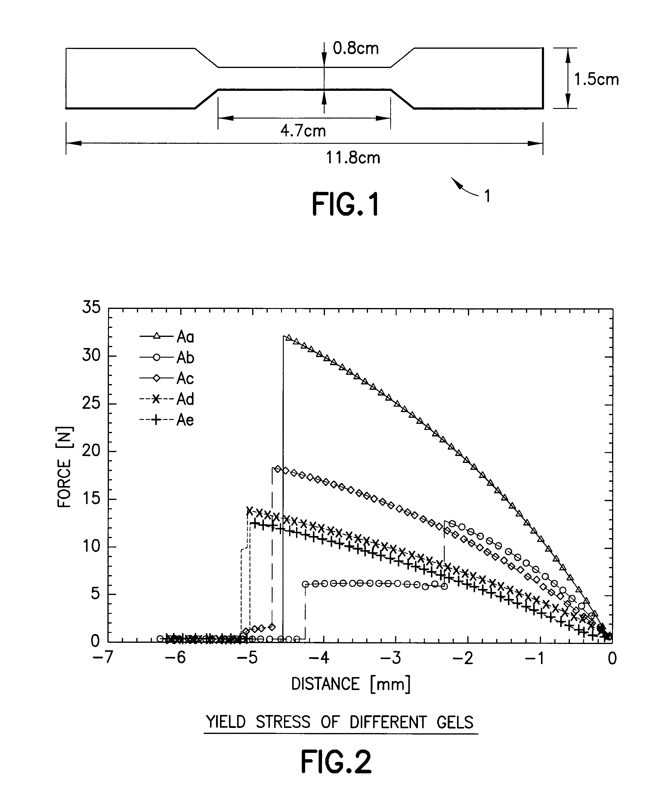
[0075]Acrylate type resins In this example the liquid composition includes components A, B, C and D:[0076]A) bisphenol A ethoxylate diacrylate (BAED)[0077]B) trimethylolpropane triacrylate (TPT)[0078]C)[0079]i. poly(ethylene glycol) diacrylate (PEGD) molecular weight 260;[0080]ii. poly(ethylene glycol) diacrylate (PEGD) m wt. 700;[0081]iii. poly(ethylene glycol) diacrylate (PEGD) m wt. 575;[0082]iv. 1,6-hexanedioldiacrylate (HDD);[0083]v. poly(ethylene glycol) dimethacrylate m wt. 330 (PEGDM)[0084]D) may be a photoinitiator ˜10 drops 2-hydroxy-2-methyl-propiophenone.

TABLE 1Acrylate based resins compositionsComponent AProduct BComponent CFormulation(15 g)(0.5 g)(5 g)AaBAEDTPTPEGD 260AbBAEDTPTHDDAcBAEDTPTPEGD 700AdBAEDTPTPEGDM 330AeBAEDTPTPEGD 575BaBAEDTPTMPEGD 260

[0085]These compositions produced hard, strong, quite brittle resins. FIG. 2 depicts tensile test data for Series Aa:Ae.

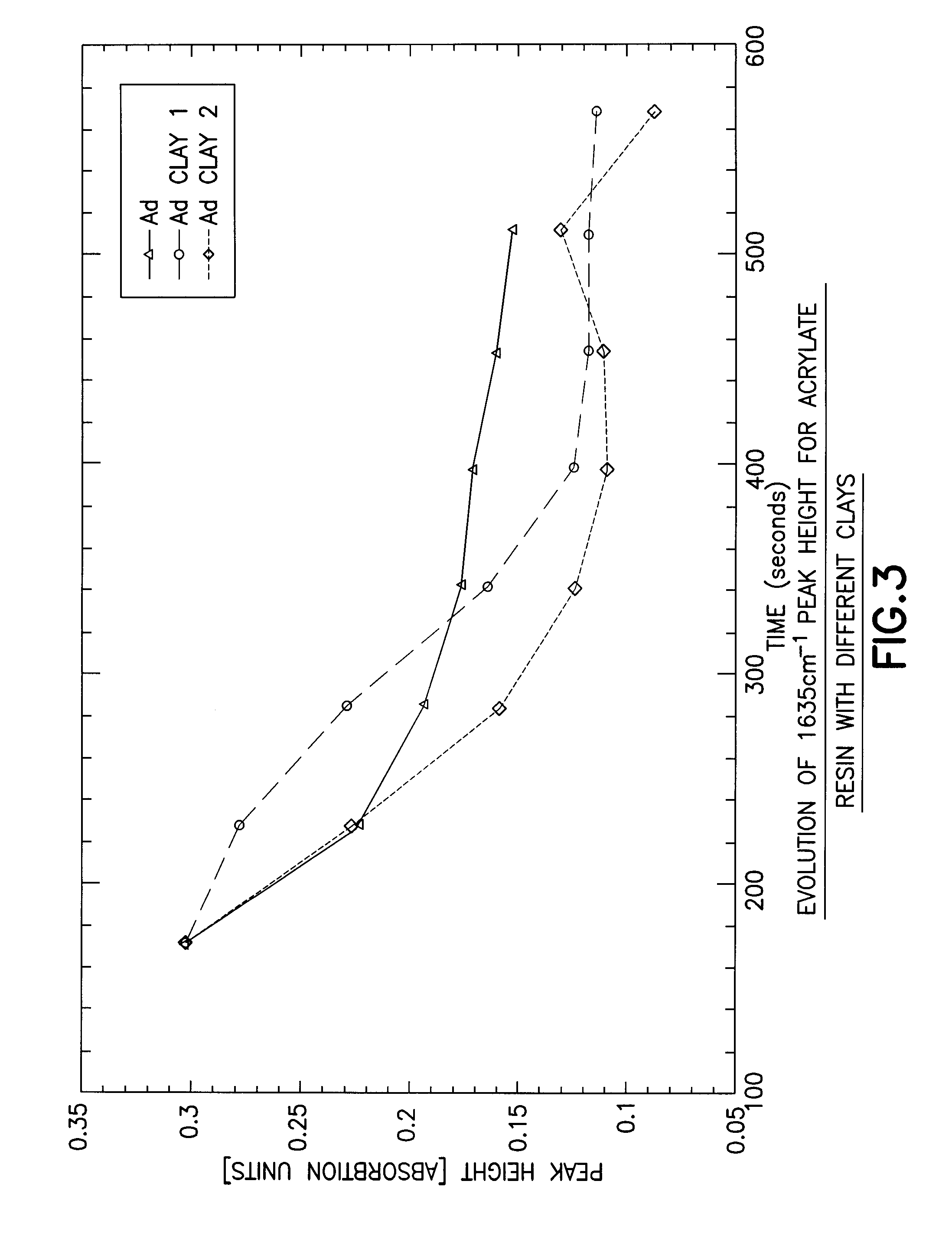
[0086]If desired, the resins can be reinforced with fillers such as clay, two examples were used: clay 1...

example 2

[0088]Divinyl ether type resins In this example, the compositions include component A, component B (cf. table 2) and C photoinitiator.[0089]A. TEGDVE: tri(ethylene glycol) divinyl ether 98%[0090]B.[0091]a. DEGDGE: di(ethylene glycol) diglycidyl ether[0092]b. GDGE: Glycerol diglycidyl ether[0093]c. NGDGE: Neopentyl glycol diglycidyl ether[0094]d. PPGDGE: Polypropylene glycol diglycidyl ether[0095]e. BDGE: 1,4-butanediol diglycidyl ether[0096]C. Photoinitiator: triarylsulfonium hexafluorophosphate salts, mixed 50% in propylene carbonate. 5:10 drops

TABLE 2Divinyl ether based resins formulationsFormulationComponent AComponent BB2aTEGDVEGDGEB2bB3aTEGDVENGDGEB3bB4bTEGDVEPPGDGEB5aTEGDVEBDGE

[0097]These formulations produced resins that ranged quite widely in softness and elasticity. Resin B1 was too soft to test in tensile mode. FIG. 5 shows tensile tests on samples of the other formulations, some in duplicate (B2, B3.).

example 3

[0098]Vinyloxybutylbenzoate type resins. In this example the compositions include the photoinitiator C, component A and one of the components listed in B.[0099]A. 4-vinyloxybutylbenzoate[0100]B. di or trivinyl ether, such as:[0101]a. bis[4(vinyloxy)butyl]succinate[0102]b. bis[4(vinyloxy)butyl]isophtalate[0103]c. tris[4(vinyloxy)butyl]trimellitate[0104]C. photoinitiator: triarylsulfonium hexafluorophosphate salts, mixed 50% in propylene carbonate (5-10 drops).

[0105]The component concentrations A and B were varied in ratio 2:1, 5:1, 10:1. Softer more elastic gels, with more rapid curing than acrylate type resins were obtained. FIG. 6 summarises test data for 2:1 ratios.

[0106]Other examples Other examples include Styrene-polybutadiene-styrene block copolymer dispersed in xylene at approximately 4 g / l, the reaction being initiated by 2-hydroxy-2-methyl-propiophenone or the triarylsulfonium hexafluorophosphate salts (50% in propylene carbonate). Both achieved a cure of a sticky gel, in 2...


PUM


Abstract

Embodiments of the present invention provide systems and methods for lining a wellbore. In certain aspects, the systems and methods comprise providing a fluid composition that is solidifiable or gellable on exposure to actinic radiation of a predetermined wavelength at the wall of open-hole wellbore and providing actinic radiation at the predetermined wavelength to solidify or gel the composition.

Description

[0001]The present invention relates to a process for lining wellbores and to a tool for producing downhole coatings for a wellbore.BACKGROUND TO THE INVENTION[0002]As a general method of forming a wellbore, e.g. for extraction of oil or gas from a formation, a drilling operation typically involves mounting a drill bit on a drilling assembly (the “bottom hole assembly”) at the lower end of a drill string and rotating the drill bit against the bottom of a hole to penetrate the formation, thereby creating a wellbore.[0003]A drilling fluid, such as a “drilling mud”, typically circulates down through the drill string, passes via the drill bit, and returns back to the surface, usually in the annular portion between the drill string and the wall of the wellbore. The drilling fluid serves a number of purposes, including lubricating the drill bit and cooling the drilling assembly. However, the drilling fluid can also be suitably pressurized to provide sufficient hydrostatic pressure at the w...

Claims


Application Information

Patent Timeline
IPC IPC(8): E21B23/00B05B5/14
CPCC09K8/508E21B33/138C09K8/516
Inventor BAILEY, LOUISECOOK, JOHNPAYEN, ARMELLEDANIEL, SYLVIEALLOUCHE, MICKAEL
Owner SCHLUMBERGER TECH CORP
Learn More