System and Distribution Tank for Low-Energy Network

a low-energy network and distribution tank technology, applied in the direction of heat pumps, heating types, lighting and heating apparatus, etc., can solve the problems of significant consumption of heating energy in properties, difficulty in placing horizontal pipes in parks, and significant loose ground on top of rocks, so as to facilitate the implementation of the system, reduce the thickness of the isolation of the first main pipe, and reduce the effect of heat transfer

Inactive Publication Date: 2009-04-02
MATEVE OY
View PDF20 Cites 11 Cited by
  • Summary
  • Abstract
  • Description
  • Claims
  • Application Information

AI Technical Summary

Benefits of technology

[0014]For example, a network extension may be connected by means of a main pipework and distribution reservoirs to any distribution reservoir of a network implemented in circuit form. In this case, the distribution reservoirs separate from the circuit serve as terminating distribution reservoirs.
[0015]In accordance with an embodiment, first distribution reservoirs and second distribution reservoirs are interconnected in the distribution tank. The distribution reservoirs are arranged in the distribution tank in such a manner that an isolation section for decreasing heat transfer between the reservoirs is arranged between the distribution reservoirs.
[0016]The distribution tanks are connected with a first main pipe for transferring transfer solution cooled with a terminal, such as a geothermal pump or the like, and with a second main pipe for transferring transfer solution heated in the ground circuit. The first main pipe can be isolated, allowing main pipes to be placed in each other's vicinity without any significant heat transfer therebetween. The thickness of the isolation of the first main pipe may be increased or decreased depending on the installation depths of the main pipes or the distance therebetween. Preferably, the main pipes may be placed in the same dug ditch on top of each other, which eliminates the need to dig separate ditches. The depth of placement of the main pipes may vary, but it may be 1 to 2 meters, for example, allowing a non-isolated main pipe to receive heat from the ground.
[0017]The second main pipe is non-isolated in a manner allowing thermal energy to transfer between the transfer liquid in the

Problems solved by technology

The consumption of heating energy in properties is significant under cold weather conditions.
However, such a pipework requires a wide surface area, which renders it usable only in large plots of land.
The placement of a horizontal pipe in a park, for example, is difficult without harming plants and roots of trees.
However, a significant layer of loose ground may exist on top of the rock.
The loose ground has to be provided with a protecting tube, which raises costs.
Accordingly, ground having

Method used


Image

  • System and Distribution Tank for Low-Energy Network
  • System and Distribution Tank for Low-Energy Network
  • System and Distribution Tank for Low-Energy Network

Examples


second embodiment

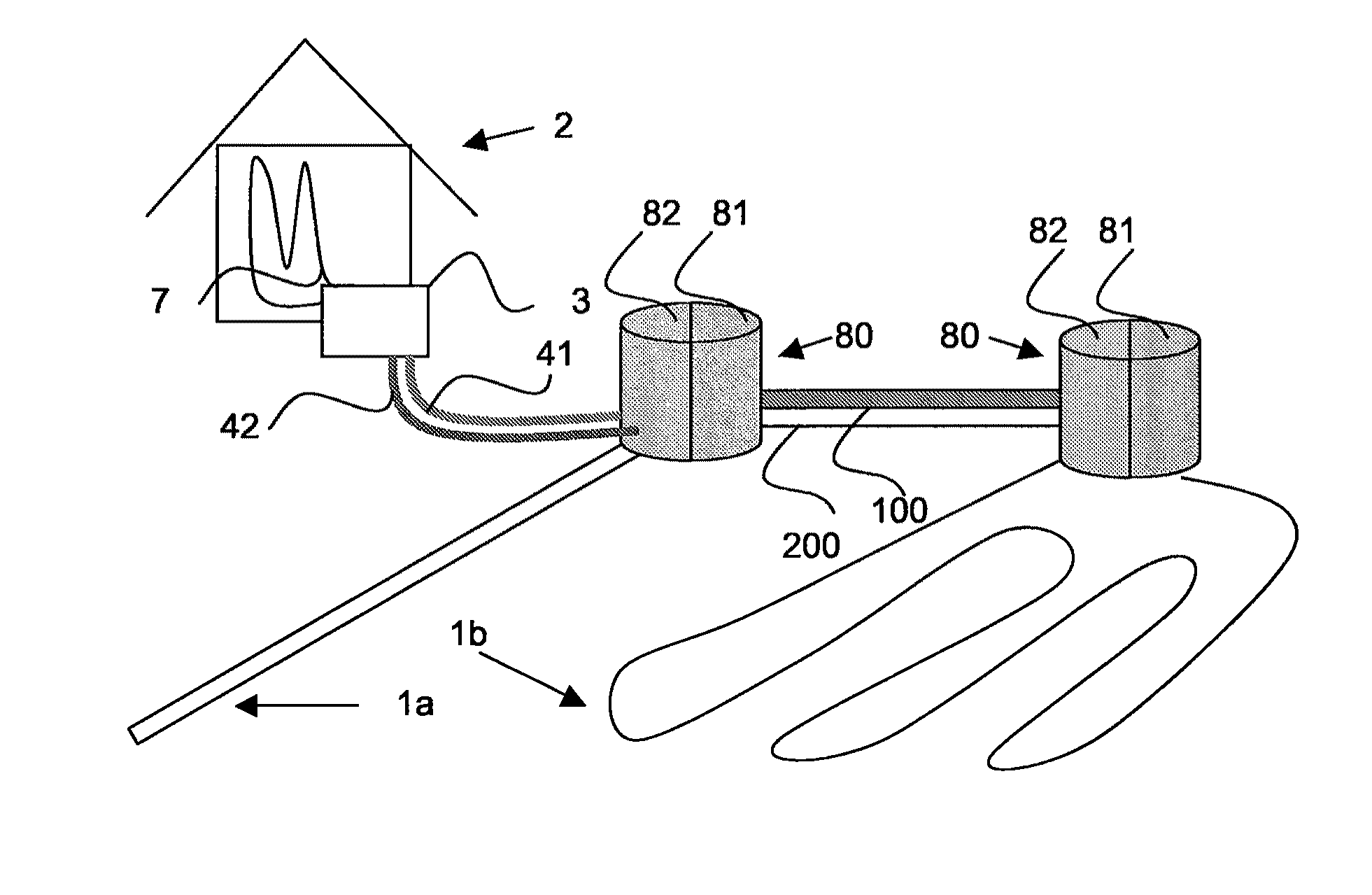
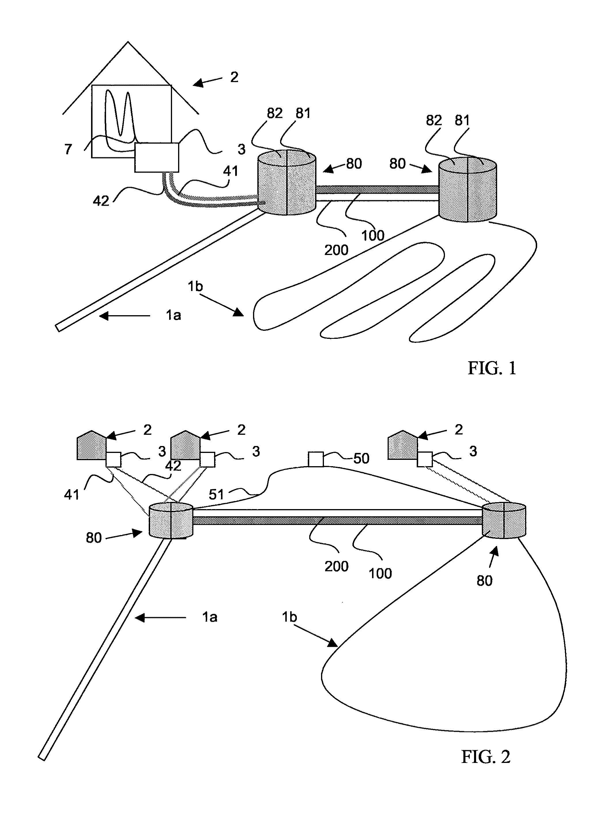
[0036]FIG. 2 shows the system according to the present invention. The terminals 3 of two houses 2 are connected to the distribution tank 80 located on the left, the terminal 3 of one house 2 being connected to the distribution tank located on the right. The flow in the collector pipes connected to the distribution tanks 80 is controlled with a control system 50. In the case of heating, wherein for instance the terminal 3 starts and when the transfer liquid of collector circuit 1b is warmer than the liquid of collector circuit 1a, the control system is able to restrict the flow of collector circuit 1a and increase the flow of collector circuit 1b such that the terminal is able to receive transfer liquid that is as warm as is preferable in view of performance. In the case of cooling, the situation is naturally reversed.

[0037]The control system 50 includes preset data for each collector circuit connected thereto and is able to use the data to restrict or increase the flow of each colle...

third embodiment

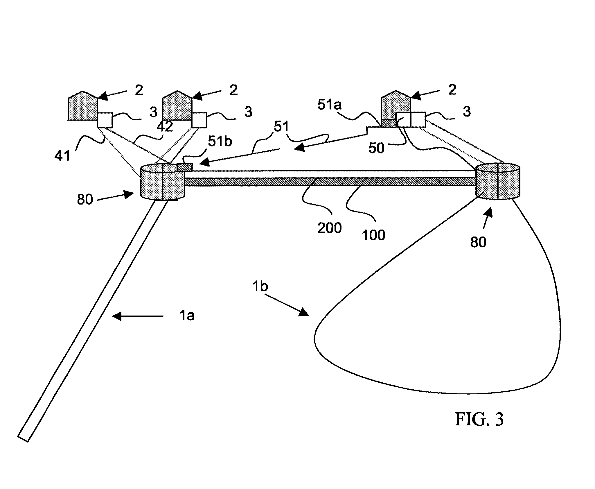
[0038]FIG. 3 shows the system according to the present invention, wherein the control system 50 is connected to one distribution tank by a wired connection and to another distribution tank 80 by a wireless connection. In the case of the wireless connection, the control system 50 and the distribution tank are provided with appropriate transmission and reception means 51a, 51b. The control system 50 is preferably connected to an information network, such as the Internet. This enables remote monitoring and control of the system.

[0039]FIG. 4 shows a front view of an embodiment of the distribution tank according to the present invention. The distribution tank 80 comprises a first reservoir 81 and a second reservoir 82, of which the first reservoir 81 is intended to receive and transfer heated transfer liquid, the second reservoir 82 being intended to receive and transfer cooled transfer liquid. The reservoirs comprise main pipe receiving means 110, 120 for receiving the main pipes 100, 2...


PUM


Abstract

A system for a low-energy network includes a collector circuit (1a, 1b) filled with a first transfer solution, a heat transfer circuit (7) filled with a second transfer solution, and a terminal (3) adapted to transfer heat between the transfer solutions of the collector circuit (1a, 1b) and the heat transfer circuit (7). The collector circuits (1a, 1b) are connected to the terminal via two distribution reservoirs (82, 81), of which the first distribution reservoir (81) is isolated and configured to receive and transfer heated transfer liquid, and the second distribution reservoir (82) is configured to receive and transfer cooled transfer liquid, and at least one collector circuit (1a, 1b) connecting the first distribution reservoir (81) and the second distribution reservoir (82) is connected to each distribution reservoir (81, 82) terminating the low-energy network. The system may also include a distribution tank (80) for the low-energy network.

Description

CROSS-REFERENCE TO RELATED APPLICATIONS[0001]This application is a Section 371 of International Application No. PCT / FI2007 / 050140, filed Mar. 15, 2007, which was published in the English language on Sep. 27, 2007, under International Publication No. WO 2007 / 107629 A1 and the disclosure of which is incorporated herein by reference.BACKGROUND OF THE INVENTION[0002]The invention relates to the utilization of low energy, such as geothermal heat, and particularly to a system for transferring heat with a terminal, such as a heat pump or the like, from the earth or water via a transfer medium.[0003]In present practice, the utilization of low energy obtained from the earth, water or rock refers to heating of a building and service water by means of a pump and a heat collector circuit. The operating principle of such a geothermal heat system corresponds to that of a freezer, but is reverse: the system cools the earth and heats a water accumulator, for example. Often 2 to 3 units of heat are ...

Claims


Application Information

Patent Timeline
IPC IPC(8): F24J3/08F28D15/00F24V50/00
CPCY02E10/12F24J3/081F24T10/10F24T10/30Y02E10/10Y02E60/14F24D15/04F25B30/06F28D20/00
Inventor PANULA, ERKKI-JUSSILIESKOSKI, MAURI
Owner MATEVE OY
Why Eureka
Try Eureka