Cookware Handle with Compressible Grip

Inactive Publication Date: 2009-04-02
SEB SA
View PDF10 Cites 2 Cited by
  • Summary
  • Abstract
  • Description
  • Claims
  • Application Information

AI Technical Summary

Benefits of technology

[0005]The objective of this invention is to offer a solution for the aforementioned disadvantages and to provide a cookware handle with optimal ergonomics, in which the shape of the grip can conform to the shape of the user's hand.
[0007]Another objective of the invention is to provide a cookware handle with a simple design that is inexpensive to implement.

Problems solved by technology

However, this construction does not make it possible to compress the grip so that its shape conforms to the shape of the user's hand when the handle is grasped and manipulated.

Method used


Image

  • Cookware Handle with Compressible Grip
  • Cookware Handle with Compressible Grip
  • Cookware Handle with Compressible Grip

Examples


Embodiment Construction

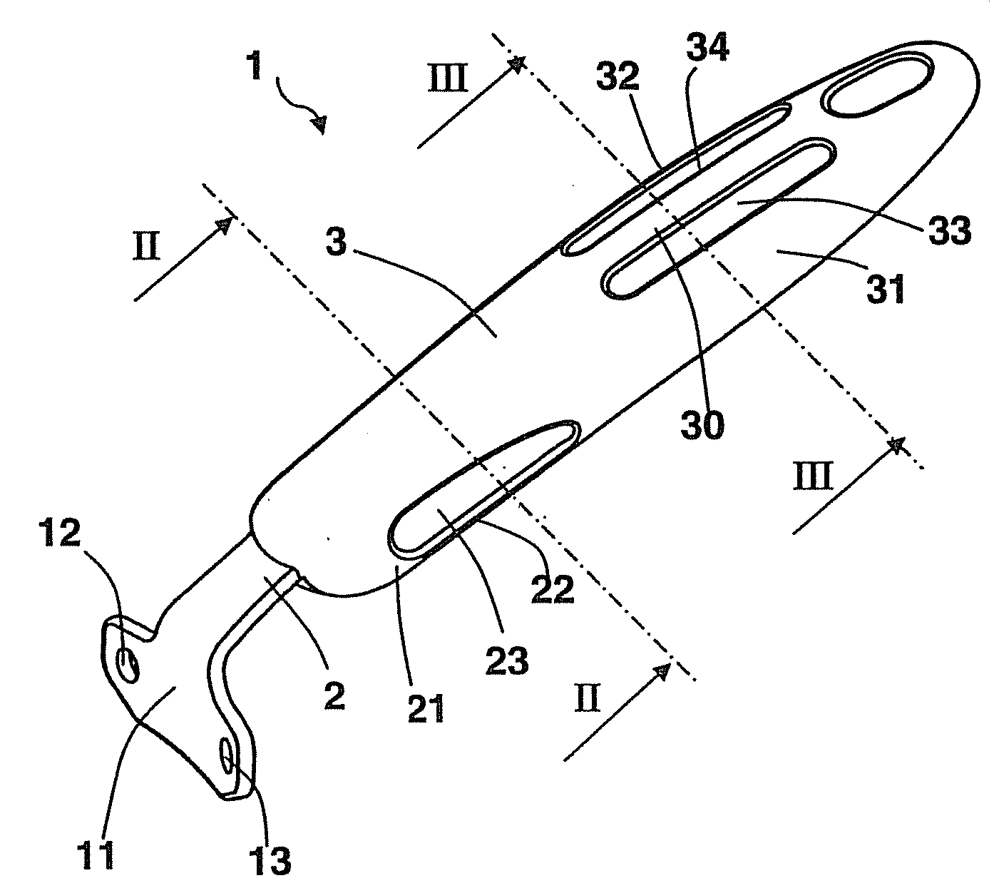
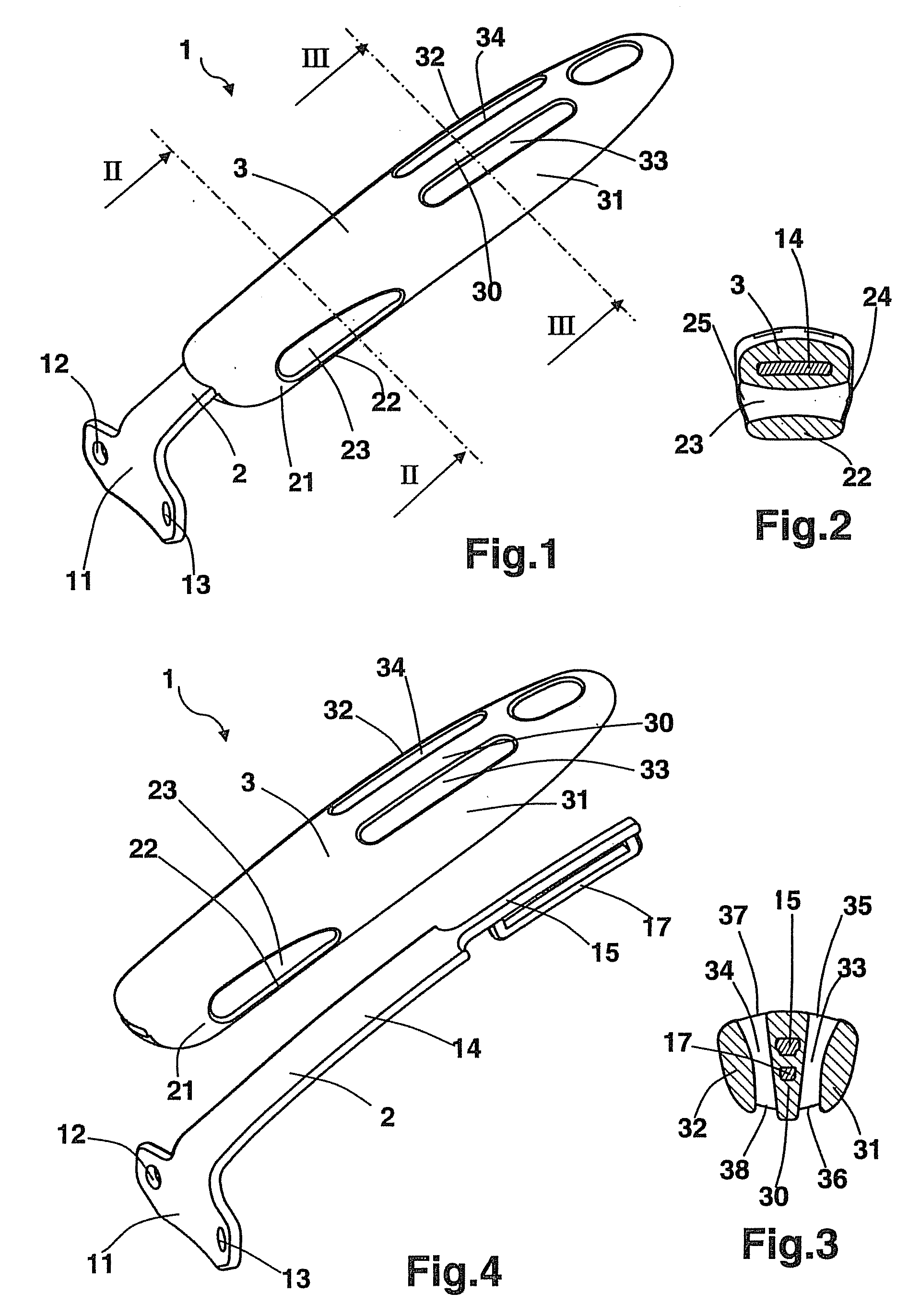
[0035]As depicted in FIGS. 1 to 4, the cookware handle 1 consists of a rigid structure 2 and a grip 3 surrounding the rigid structure 2.

[0036]The rigid structure 2 consists of a front part 11 designed to be placed against the curved edge of the cookware (not shown). The front part 11 has a means of being attached to the curved edge, such as two openings 12, 13 that can accommodate two rivets.

[0037]From the front part 11, there is a rigid structure 2 consisting of a shaft 14 with a cross section that is roughly rectangular in shape, extending lengthwise. The shaft 14 consists of a thinner back part 15 that is reinforced by an arch 17 positioned underneath this back part 15.

[0038]The grip 3 is cast molded onto the shaft 14 of the rigid structure 2, giving said grip 3 an ergonomic shape designed to be grasped by the user's hand. The grip 3 is made of a flexible silicone material.

[0039]The grip 3 has a lower front part 21 consisting of a wall 22 positioned roughly horizontally and facin...


PUM


Abstract

A cookware handle designed to be grasped by a user's hand, consisting of a rigid structure attached to the cookware, and a flexible grip surrounding the rigid structure. The flexible grip has at least one part consisting of a wall that is from 2 to 10 mm thick, and preferably 5 mm thick, that creates a hand support surface, and at least one hollow cavity inside the grip is adjacent to the wall to enable said wall to be compressed when the handle is grasped.

Description

BACKGROUND OF THE INVENTION[0001]1. Field of the Invention[0002]This invention pertains to a handle for cookware such as a saucepan or frying pan.[0003]2. Description of Related Art[0004]In prior art, and specifically in Document EP 1704804, we have seen a handle with a rigid structure and a grip surrounding the structure. The grip is made of a material that conducts heat less than the material of which the structure is made and has an ergonomic shape that makes the handle easy to hold. However, this construction does not make it possible to compress the grip so that its shape conforms to the shape of the user's hand when the handle is grasped and manipulated.[0005]The objective of this invention is to offer a solution for the aforementioned disadvantages and to provide a cookware handle with optimal ergonomics, in which the shape of the grip can conform to the shape of the user's hand.[0006]Another object of the invention is to provide a cookware handle that makes it possible to ma...

Claims


Application Information

Patent Timeline
IPC IPC(8): B25G1/10
CPCA47J45/061Y10T16/476Y10T16/466Y10T16/498
Inventor PASQUINI, LUDOVIC
Owner SEB SA
Why Eureka
Try Eureka