
Fluorescence filtering system and method for molecular imaging

Inactive Publication Date: 2009-03-26
LI COR
View PDF16 Cites 23 Cited by
  • Summary
  • Abstract
  • Description
  • Claims
  • Application Information

AI Technical Summary

Benefits of technology

[0011]Various embodiments provide highly efficient and uniform methods of illumination. The methods are particularly suitable for wide-field fluorescence imaging with laser excitation. When coupled with the field-uniform filtering methods described herein, these methods produce field independent quantitative fluorescence measurement.

Problems solved by technology

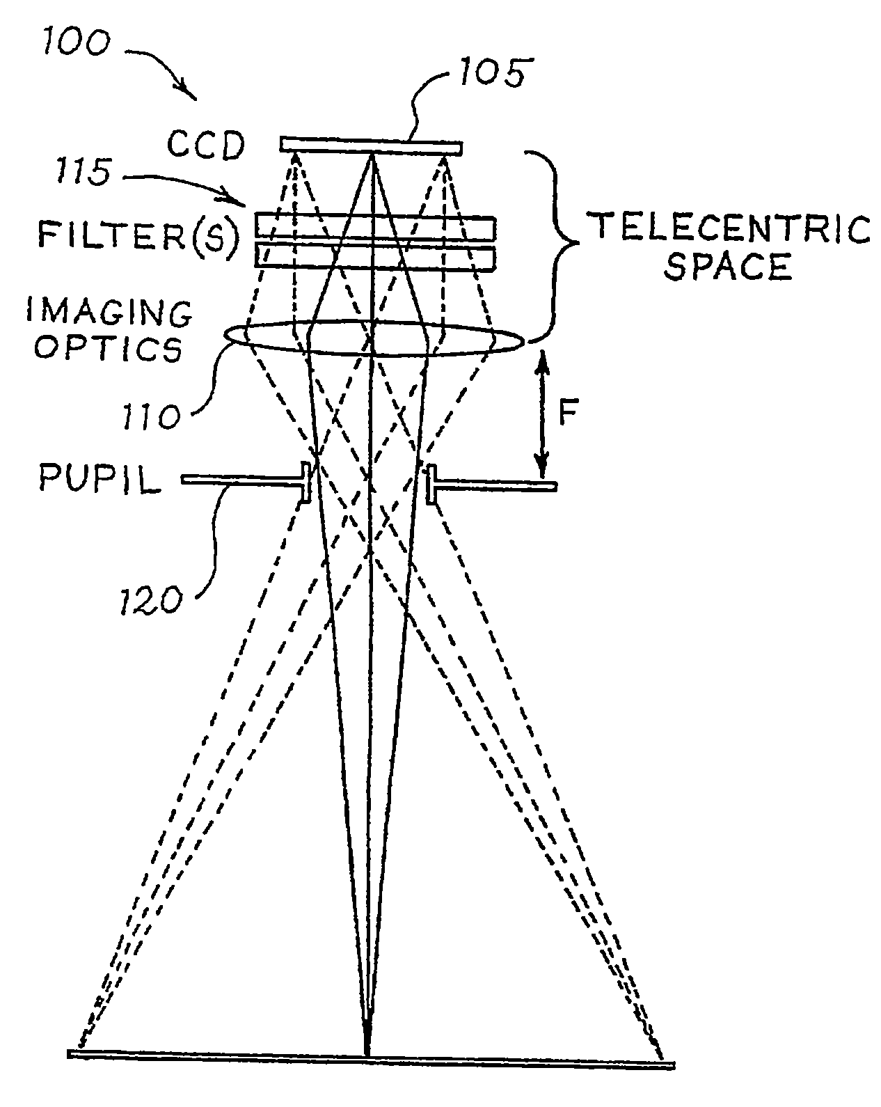
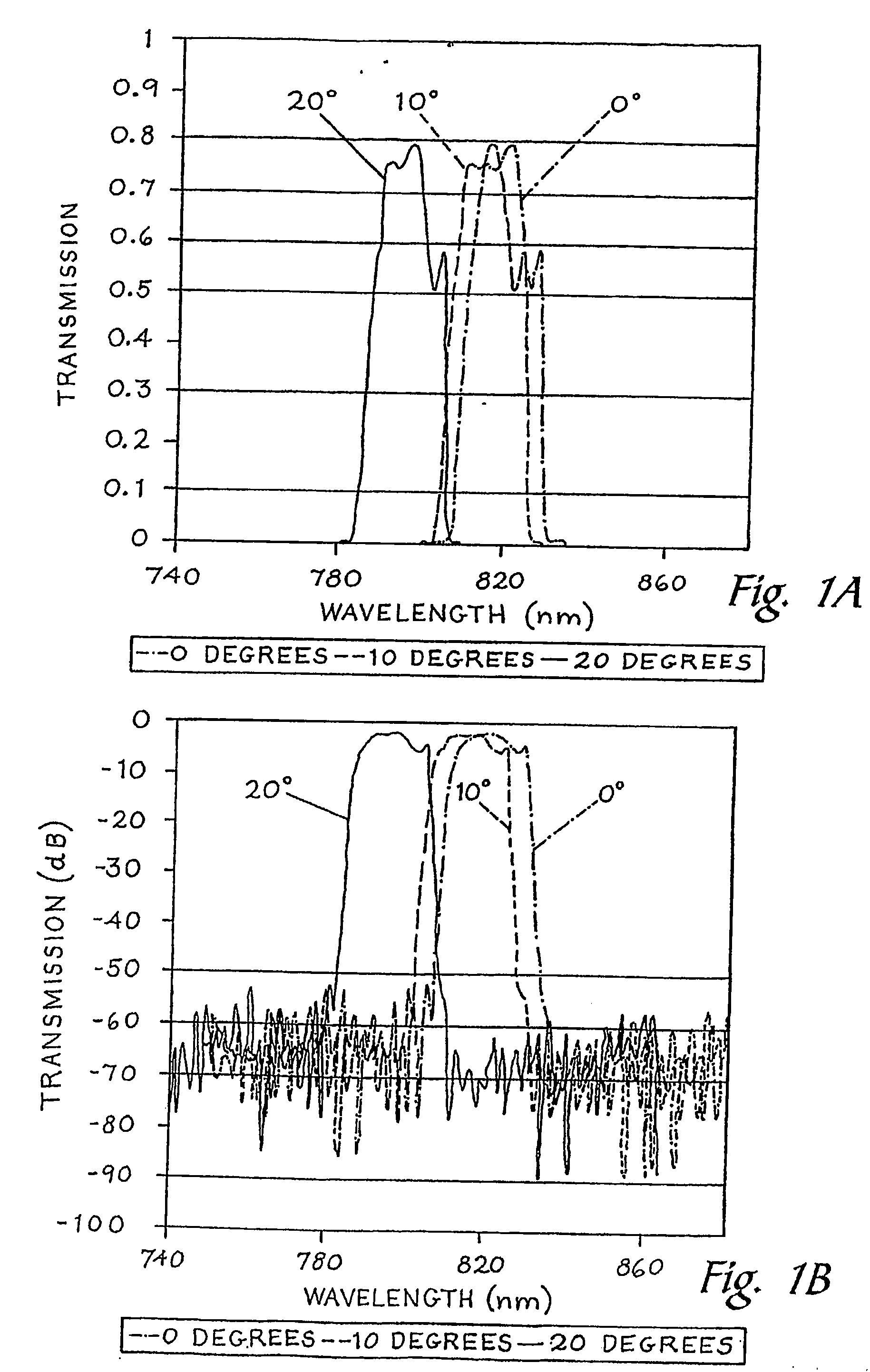
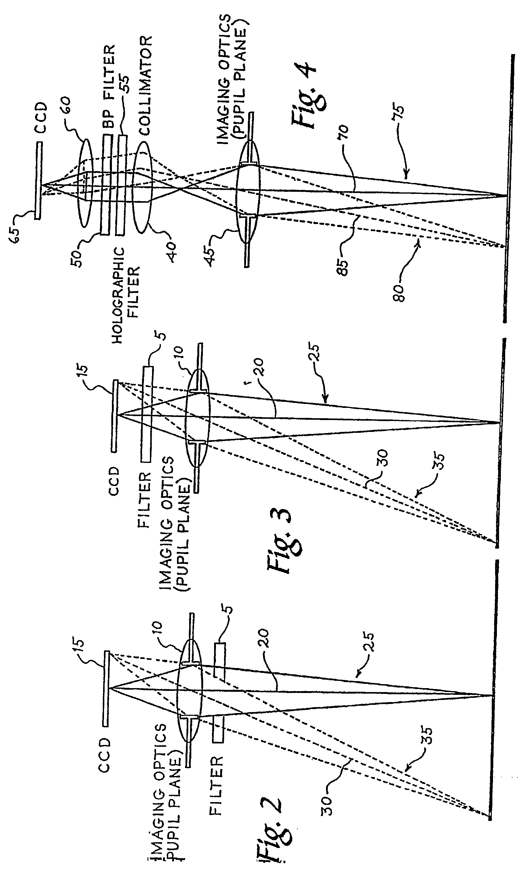
One challenge with emission filters is that unwanted photon rejection depends on the angle at which light traverses the filter.
This results in different amounts of excitation leakage across the field.
The various types of illumination methods in use today share a common set of limitations: they generally suffer from low efficiency and / or produce ‘hot’ areas, typically in the center of the field of view.
These methods tend to suffer from low overall efficiency, not so great uniformity, and produce a significant amount of stray light that can present other challenges to obtaining good quality imaging.
Other methods take the approach of using more condensed illumination techniques, such as using light-guides, that can be more efficient but do not generally produce uniform illumination.
Laser sources, on the other hand, have limited angular extent and therefore can be managed more efficiently but present more challenges to producing uniform illumination.

Method used


Image

  • Fluorescence filtering system and method for molecular imaging
  • Fluorescence filtering system and method for molecular imaging
  • Fluorescence filtering system and method for molecular imaging

Examples


Embodiment Construction

[0038]Fluorescence detection is a tool for molecular imaging. It enables researchers to detect particular components of complex bio-molecular assemblies, such as in live cells. Fluorescence is a photo-physical process that involves the interaction of light with certain molecules called fluorophores or fluorescent dyes. It consists of the absorption of light energy at the appropriate wavelength by such molecules and the subsequent emission of other light photons at longer wavelengths. The wavelength ranges that a fluorophore molecule can absorb and emit at are called absorption and emission bands, respectively.

[0039]A fluorescence optical system illuminates a fluorophore-labeled target with light whose wavelength content falls within the absorption band and collects light whose wavelength content is in the emission band. The source(s) and optics that generate the illumination part of the system are called the “excitation optics,” and the optics used to collect the fluorescence emissi...


PUM


Abstract

An optical system is disclosed that can be used for fluorescence filtering for molecular imaging. In one preferred embodiment, a source subsystem is disclosed comprising a light source and a first set of filters designed to pass wavelengths of light in an absorption band of a fluorescent material. A detector subsystem is also disclosed comprising a light detector, imaging optics, a second set of filters designed to pass wavelengths of light in an emission band of the fluorescent material, and an aperture located at a front focal plane of the imaging optics. A telecentric space is created between the light detector and the imaging optics, such that axial rays from a plurality of field points emerge from the imaging optics parallel to each other and perpendicular to the second set of filters.

Description

CROSS-REFERENCES TO RELATED APPLICATIONS[0001]The present application claims priority to, and is a Continuation-in-Part of, PCT Application No. PCT / US2006 / 005341, filed on Feb. 15, 2006. The present application also claims priority to U.S. Provisional Application No. 61 / 055,885, filed on May 23, 2008. The disclosures of both PCT / US2006 / 005341 and U.S. Provisional Application No. 61 / 055,885 are hereby incorporated by reference in their entireties for all purposes.BACKGROUND[0002]The present invention relates generally to optical imaging, and more particularly to systems and methods for providing uniform illumination for optical imaging applications such as fluorescence imaging.[0003]A fluorescence optical system illuminates a fluorophore-labeled target with light whose wavelength content falls within the absorption band and collects light whose wavelength content is in the emission band. An emission filter placed in front of a detector filters light that is not in the emission band. ...

Claims


Application Information

Patent Timeline
IPC IPC(8): G02B27/20F21S8/00G01J1/58
CPCG01J3/0208G01J3/12G01J2003/1213G01J2003/1226A61B5/0071G01J3/10G01J2003/104G01J3/4406G01N21/6456
Inventor BOUZID, AHMEDLAMB, DONALD T.RAGATZ, ANDREW G.MIDDENDORF, LYLE R.
Owner LI COR
Learn More