
Electronic synchronous/asynchronous transceiver device for power line communication networks

a transceiver device and power line technology, applied in powerline communication applications, instruments, baseband system details, etc., can solve the problems of high overall cost, high complexity of known circuits, and high cost to render them unusable for low-cost applications, and achieve low cost.

Active Publication Date: 2009-03-19
STMICROELECTRONICS SRL
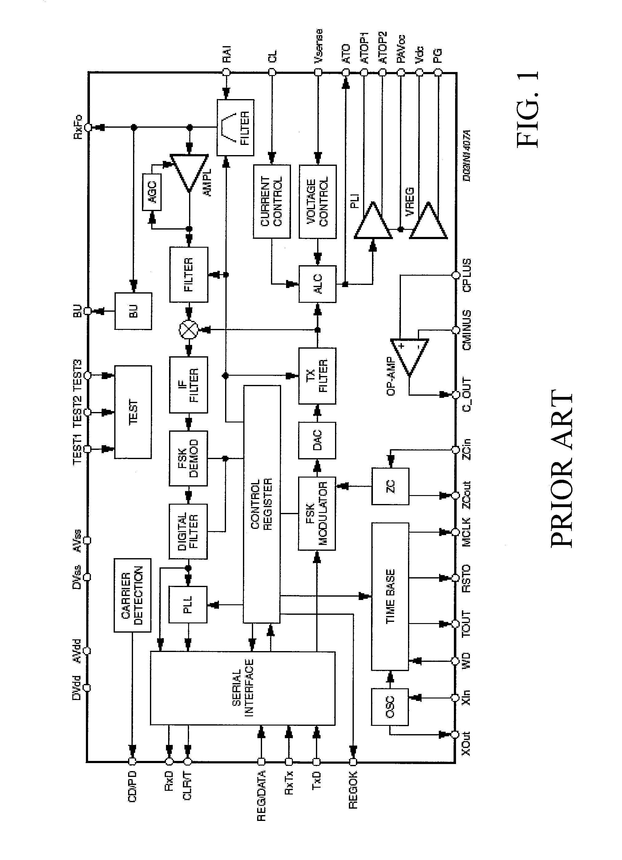
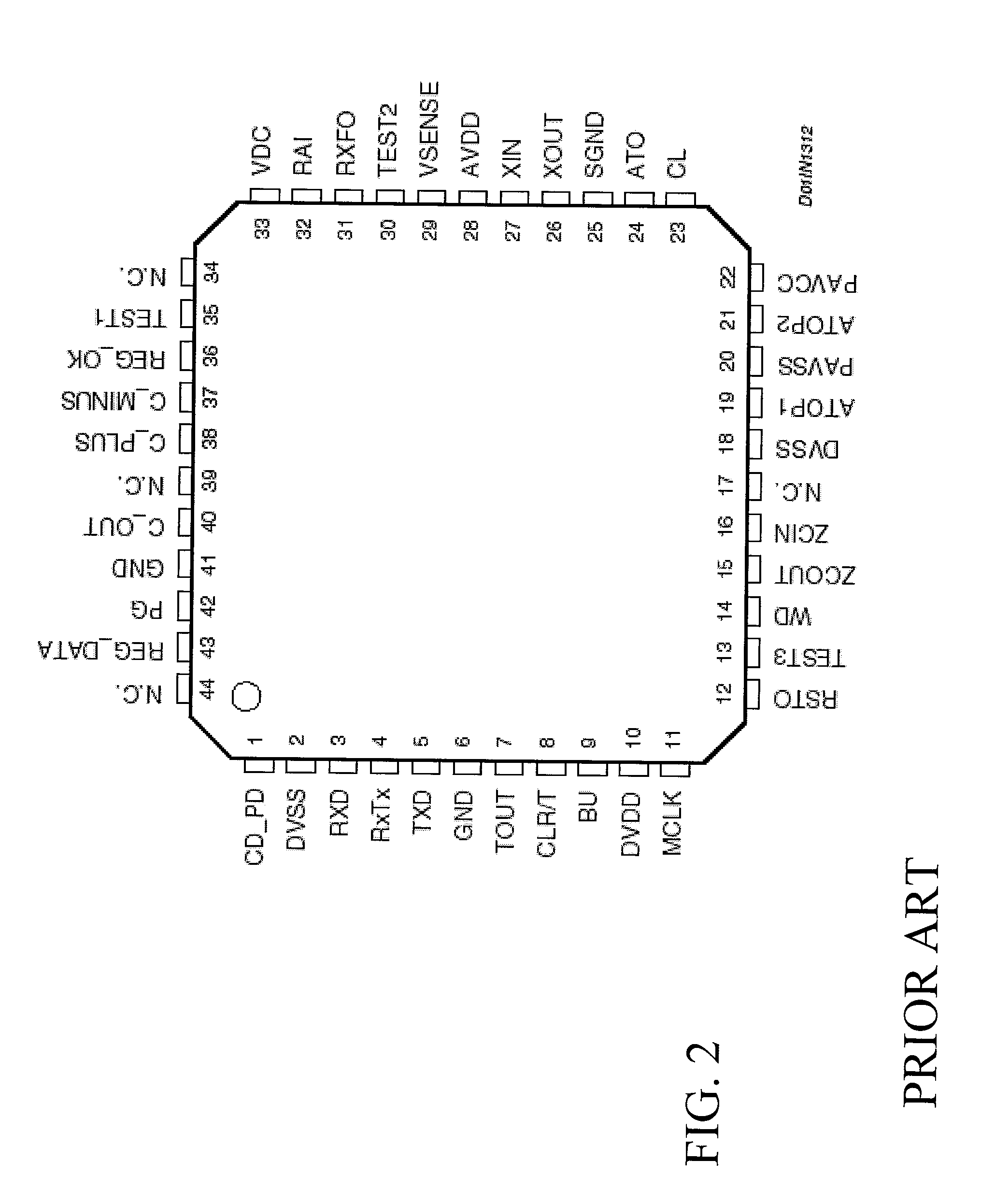
View PDF15 Cites 12 Cited by
  • Summary
  • Abstract
  • Description
  • Claims
  • Application Information

AI Technical Summary

Benefits of technology

[0029]One embodiment is a new power line transceiver device having structural and functional features that allow a simpler connection with a host controller while improving the device linear power performances and reducing the device overall consumption.
[0030]The power line transceiver device has a reduced integrated circuit area and is more cost-effective if compared with the prior art solutions.

Problems solved by technology

While being advantageous under many points of view and substantially providing a solution for a large spectrum of modem communication this known circuit is very complex and also very expensive to render it unusable for low cost applications.
For instance, the currently high demand of “outdoor” applications, such as small street lighting controllers and cost effective Automatic Meter Reading (AMR) systems may not be satisfied by the use of the above mentioned prior art solution, if not supporting a higher overall cost.
Moreover, the prior art circuit cannot supply different kinds of controllers that may be connected to the transceiver device in specific applications; this compels providing specific circuit portions on board of each single controller.

Method used


Image

  • Electronic synchronous/asynchronous transceiver device for power line communication networks
  • Electronic synchronous/asynchronous transceiver device for power line communication networks
  • Electronic synchronous/asynchronous transceiver device for power line communication networks

Examples


Embodiment Construction

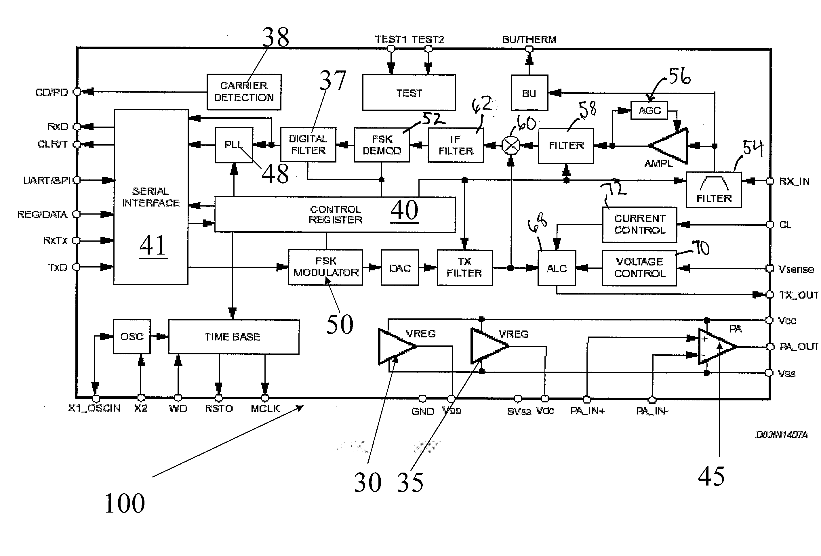
[0056]According to one embodiment, for instance the embodiment shown in FIG. 3, a new electronic power line transceiver device 100 is disclosed for applications on power line communication networks.

[0057]More specifically, the transceiver device 100 is a half duplex synchronous / asynchronous binary-FSK (frequency shift keying) modem device that may be employed in narrowband power line communication applications, in particular for compact and cost-sensitive command and control systems.

[0058]Such a modem device is realized as a single integrated circuit operating from a single supply voltage. The modem device 100 incorporates at least a line driver 45 and at least two linear regulators 35, 30 for 5V and 3.3V, respectively.

[0059]The device operation is controlled by means of an internal register 40 that is programmable through a synchronous serial interface 41.

[0060]Additional functions such as: watchdog, clock output, output voltage and current control, preamble detection, time-out and...


PUM


Abstract

An electronic synchronous / asynchronous transceiver device for power line communication networks is integrated into a single chip and operates from a single supply voltage. The transceiver device includes: at least an internal register that is programmable through a synchronous serial interface; at least a line driver for a two-way network communication over power lines implemented by a single ended power amplifier with direct accessible input and output lines that is part of a tunable active filter for the transmission path; and at least a couple of linear regulators for powering with different voltage levels different kind of external controllers linked to the transceiver device.

Description

REFERENCES TO RELATED APPLICATIONS[0001]This application is a continuation-in-part of International Patent Application No. PCT / IT2006 / 000166, filed Mar. 17, 2006, now pending, which application is incorporated herein by reference in its entirety.BACKGROUND[0002]1. Technical Field[0003]The present invention relates to an electronic synchronous / asynchronous transceiver device, for instance for power line communication networks and similar systems. More specifically, the invention relates to a transceiver device for power line communication networks of the type integrated into a single chip and operating from a single supply voltage.[0004]2. Description of the Related Art[0005]In this specific technical field it is known on the market a circuit transceiver named “ST7538” which is a half duplex synchronous / asynchronous FSK modem designed for power line communication network applications.[0006]This known circuit operates from a single supply voltage and integrates a line driver and a 5V ...

Claims


Application Information

Patent Timeline
IPC IPC(8): H04B1/38H04L25/49
CPCH04B3/54H04B2203/5416H04B2203/5491H04B2203/5433H04B2203/5458H04B2203/5425
Inventor CAPPELLETTI, ROBERTOCANTONE, GIUSEPPEANTONELLI, BARBARACASTIGLIOLA, ANTONELLOLASCIANDARE, ALESSANDROMARANO, VINCENZO
Owner STMICROELECTRONICS SRL
Learn More