Liquid crystal display

Inactive Publication Date: 2009-03-19
SONY CORP
View PDF10 Cites 3 Cited by
  • Summary
  • Abstract
  • Description
  • Claims
  • Application Information

AI Technical Summary

Benefits of technology

[0017]These two directions have the same influence on the design of the pixel. In other words, to speed up the response, it is necessary to arrange more slits 112 as liquid crystal molecular alignment control means in one pixel. FIG. 17 shows an illustration in which the number of slits 112 of the pixel electrodes Px1 and Px2 shown in FIG. 15 is increased. However, the number of slits 112A which are allowed to be narrowed by reverse polarity driving out of 12 slits 112 on the TFT substrate is only 4. The other eight slits 112B and the slits 122 of the common electrode 121 of the facing substrate120 are forced to be designed as before. Moreover, when the size of each pixel is increased, there is a possibility that the number of slits 112 is increased more than that in FIG. 17, and it is important to further enhance an effect of narrowing a slit by reverse polarity driving.
[0018]In view of the foregoing, it is desirable to provide a liquid crystal display capable of increasing the number of slits which are allowed to be narrowed by reverse polarity driving, and further enhancing an effect of narrowing a slit.
[0020]In the liquid crystal display according to the embodiment of the invention, at least four of divided subpixel electrodes of the subpixel electrode to which a voltage having one polarity is applied are adjacent to divided subpixel electrodes of the subpixel electrode to which a voltage having the other polarity is applied on the top and bottom sides of the divided subpixel electrodes, so the divided subpixel electrodes of the subpixel electrode to which a voltage having one polarity is applied and the divided subpixel electrodes of the subpixel electrode to which a voltage having the other polarity is applied are alternately arranged. Therefore, slits between them are able to be narrowed by reverse polarity driving, and transmittance is improved by the stability of liquid crystal molecular alignment.
[0021]In the liquid crystal display according to the embodiment of the invention, at least four of divided subpixel electrodes of the subpixel electrode to which a voltage having one polarity is applied are adjacent to divided subpixel electrodes of the subpixel electrode to which a voltage having the other polarity is applied on the top and bottom sides of the divided subpixel electrodes, so more slits are able to be narrowed by reverse polarity driving. Therefore, an effect of narrowing a slit which is that liquid crystal molecular alignment is stabilized to improve transmittance is further enhanced. Moreover, when the number of slits is increased, VA mode response characteristics are able to be improved, so the liquid crystal display according to the embodiment of the invention is advantageous to speed up the response, and is extremely suitable for increasing the size of each pixel with an increase in the size of a screen.

Problems solved by technology

Moreover, when liquid crystal television screens become larger, each pixel becomes larger.

Method used


Image

  • Liquid crystal display
  • Liquid crystal display
  • Liquid crystal display

Examples


first embodiment

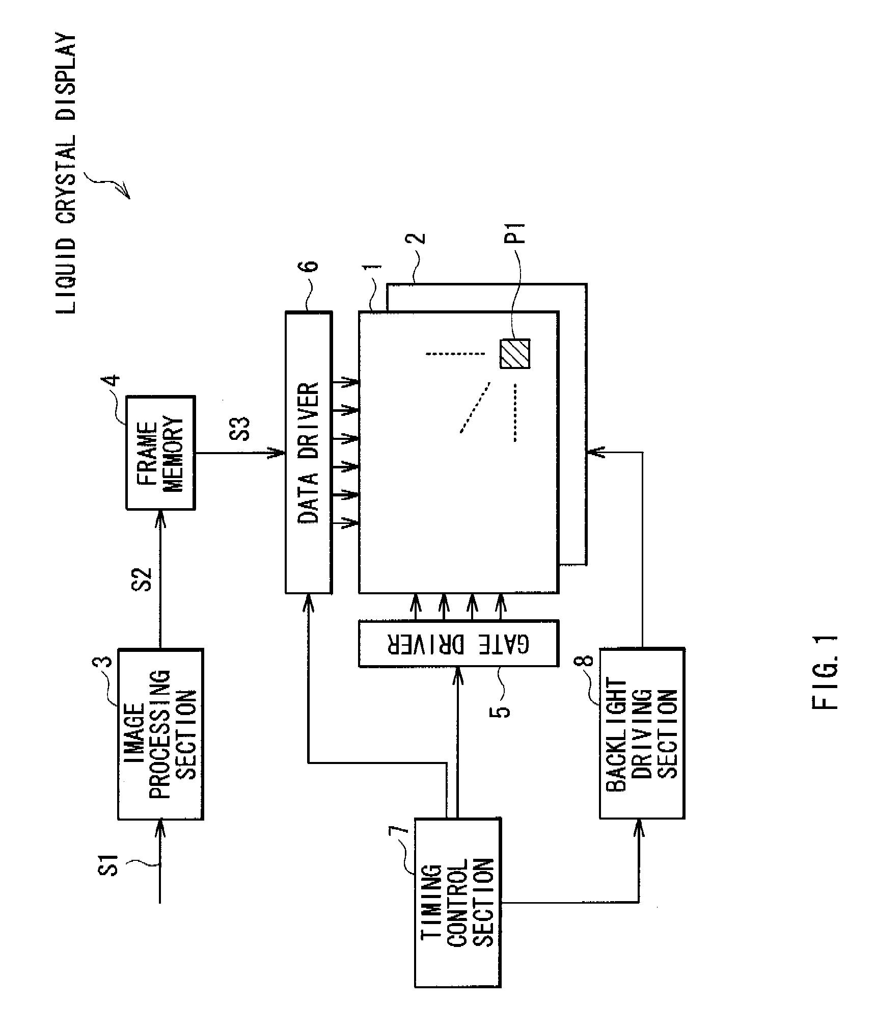
[0041]FIG. 1 shows the configuration of a liquid crystal display according to a first embodiment of the invention. The liquid crystal display is a VA mode liquid crystal display used for a liquid crystal television or the like, and the liquid crystal display includes, for example, a liquid crystal display panel 1, a backlight section 2, an image processing section 3, a frame memory 4, a gate driver 5, a data driver 6, a timing control section 7 and a backlight driving section 8.

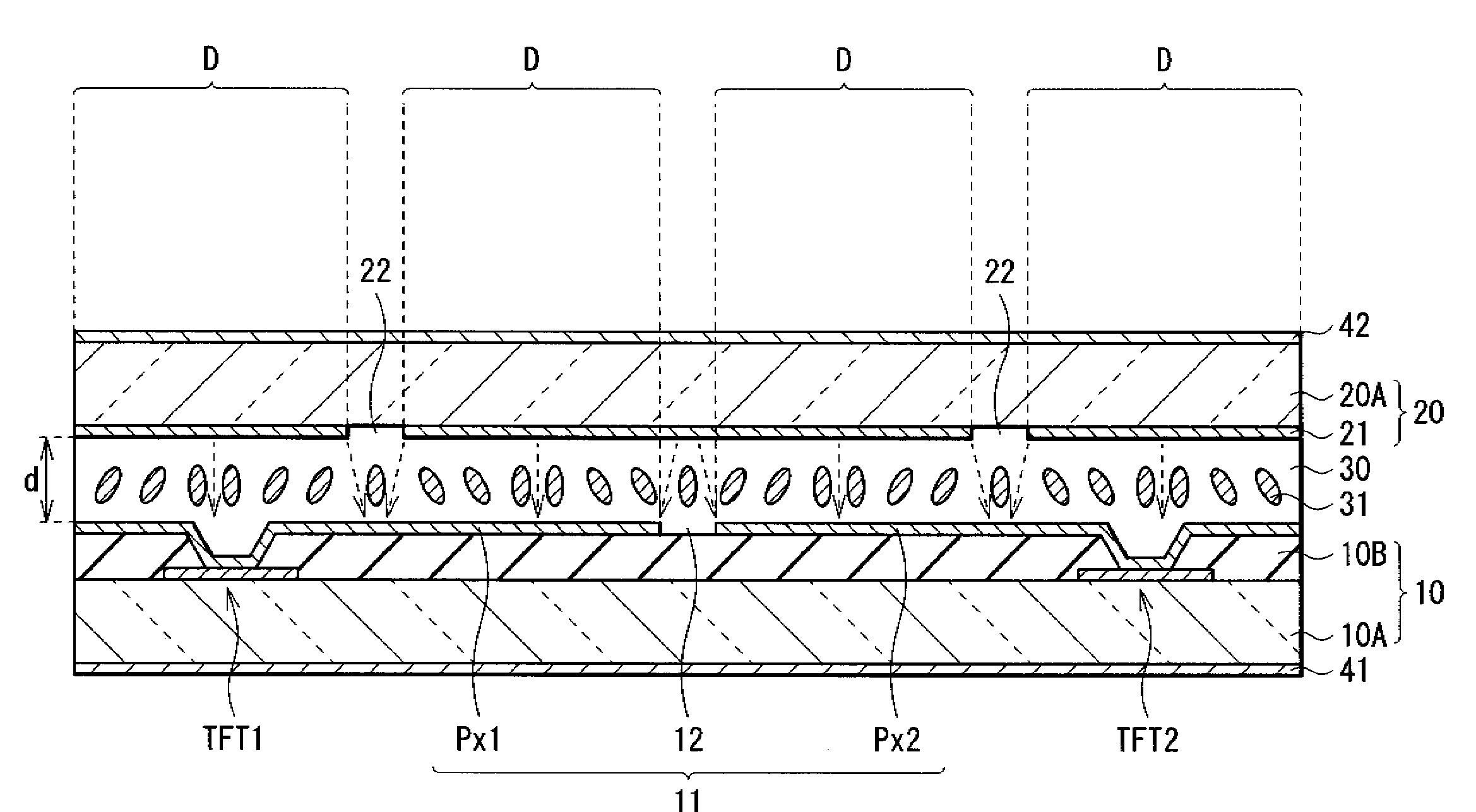
[0042]The liquid crystal display panel 1 displays an image on the basis of a video signal Di transmitted from the data driver 6 in response to a driving signal supplied from the gate driver 5, and includes a plurality of pixels P1 arranged in a matrix form, and the liquid crystal display panel 1 is an active matrix liquid crystal display panel in which each pixel P1 is driven. A specific configuration of the pixel P1 will be described later.

[0043]The backlight section 2 is a light source applying light to the...

second embodiment

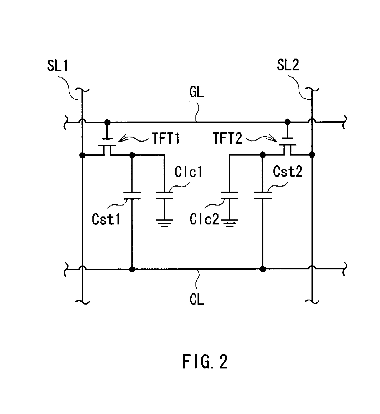
[0066]FIG. 6 shows pixel electrodes 11 of four pixels P1 which are arranged in a liquid crystal display according to a second embodiment of the invention. FIG. 7A shows the pixel electrode 11 shown at each of the upper left and the lower right in FIG. 6, and FIG. 7B shows the pixel electrode 11 at each of the upper right and the lower left in FIG. 6. In the liquid crystal display according to the embodiment, the outside shape of the pixel electrode 11 is changed to improve the transmittance in corners of the pixel P1, and except for this, the liquid crystal display according to the embodiment has the same configuration as that in the first embodiment. Therefore, like components are denoted by like numerals.

[0067]In the pixel electrodes 11 shown at the upper left and the lower right in FIG. 6, as shown in FIG. 7A, the subpixel electrode Px1 is divided into four divided subpixel electrodes Px11 to Px14, and the subpixel electrode Px2 is divided into eight divided subpixel electrodes P...


PUM


Abstract

A liquid crystal display includes a plurality of pixels arranged in a matrix form, in which each of the pixels includes a plurality of non-linear elements and a plurality of subpixel electrodes on a drive substrate, the plurality of subpixel electrodes being electrically connected to the plurality of non-linear elements, respectively, a voltage having a reverse polarity is applied to at least two of the plurality of subpixel electrodes on the same frame, and each of the at least two of the plurality of subpixel electrodes is divided into four or more divided subpixel electrodes, and at least four of the divided subpixel electrodes of the subpixel electrode to which a voltage having one polarity is applied are adjacent to divided subpixel electrodes of the subpixel electrode to which a voltage having the other polarity is applied on the top and bottom sides of the divided subpixel electrodes.

Description

CROSS REFERENCES TO RELATED APPLICATIONS[0001]The present invention contains subject matter related to Japanese Patent Application JP 2007-240811 filed in the Japanese Patent Office on Sep. 18, 2007, the entire contents of which being incorporated herein by reference.BACKGROUND OF THE INVENTION[0002]1. Field of the Invention[0003]The present invention relates to a liquid crystal display specifically suitable for VA (Vertical Alignment) mode.[0004]2. Description of the Related Art[0005]In recent years, VA mode liquid crystal displays used in liquid crystal televisions and the like have utilized a novel technique called multi-pixel to improve viewing angle characteristics in gray levels. As shown in FIG. 9, each pixel is divided into a plurality of subpixels A and B, and the subpixel A increases its intensity according to an input gray level, and then the subpixel B increases its intensity later. To obtain superior viewing angle characteristics, it is desired to reduce the area of the...

Claims


Application Information

Patent Timeline
IPC IPC(8): G09G3/36
CPCG02F1/133707G02F1/13624G02F2201/40G09G3/3611G09G2300/0426G09G2300/0447G09G2300/0491G09G2360/18G02F1/134345
Inventor KAMADA, TSUYOSHI
Owner SONY CORP
Why Eureka
Try Eureka