Method of measuring micro-structure, micro-structure measurement apparatus, and micro-structure analytical system
a microstructure and analytical system technology, applied in the direction of measurement devices, semiconductor/solid-state device testing/measurement, instruments, etc., can solve the problems of lowering the yield ratio, insufficient precision in the control of the lithographic process or etching process, and the measurement will never be applicable to samples which cannot be subjected to destructive inspection
- Summary
- Abstract
- Description
- Claims
- Application Information
AI Technical Summary
Benefits of technology
Problems solved by technology
Method used
Image
Examples
example 1
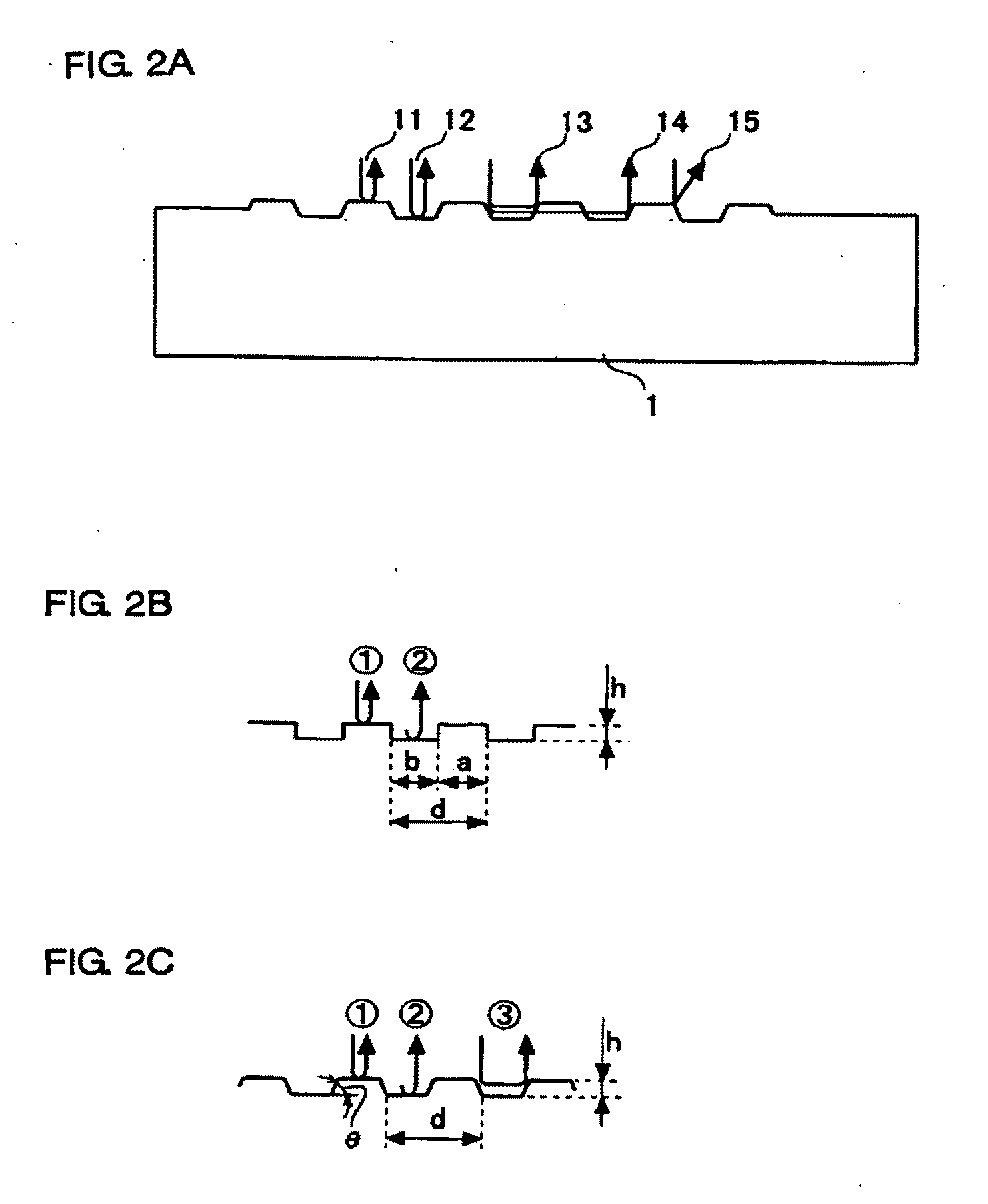
[0107]Next paragraphs will detail embodiments of the measurement apparatus and calculation procedures based on the principle of the micro-structure measurement of the present invention, referring to the attached drawings.
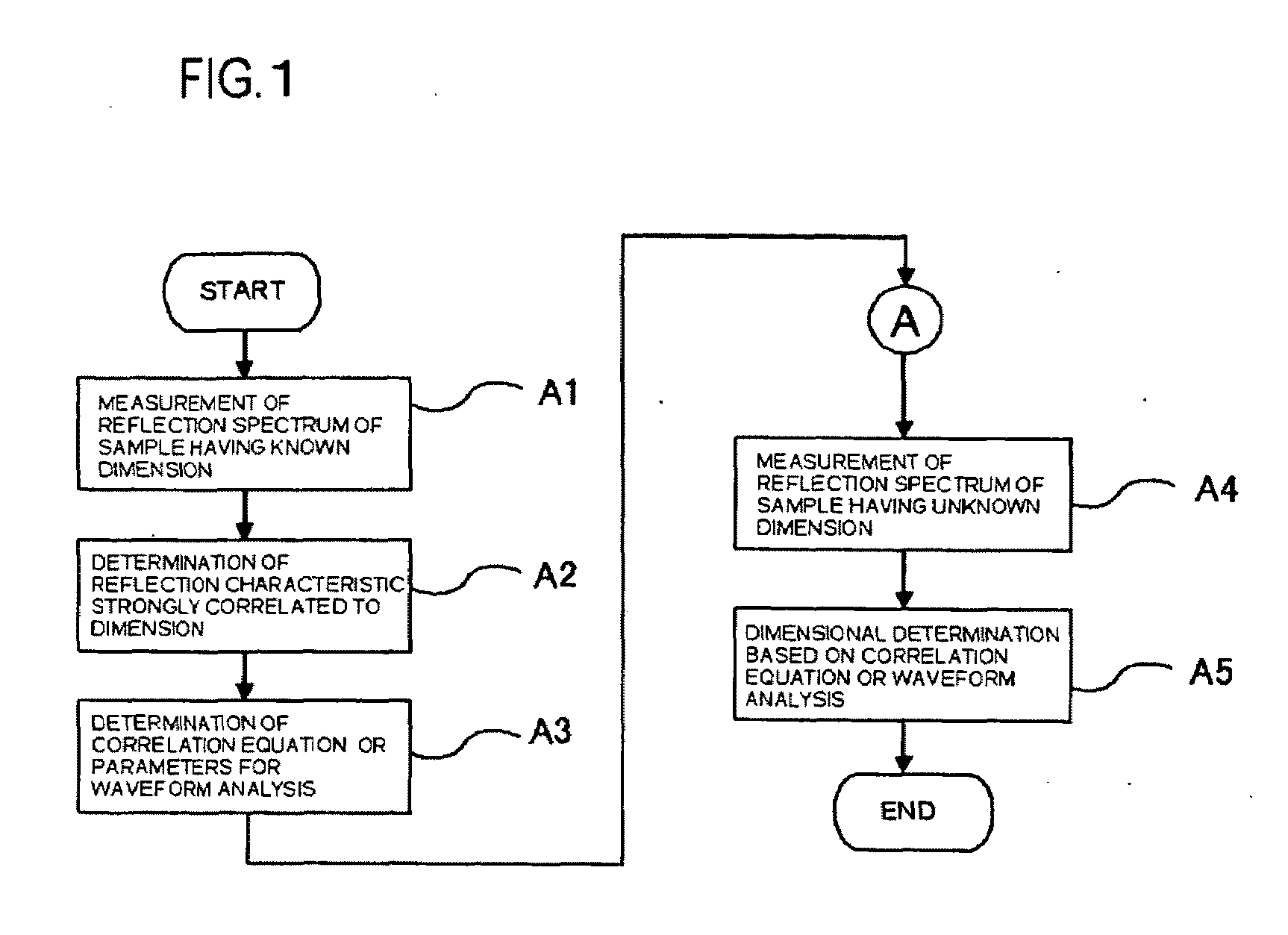
[0108]FIG. 6 shows a block diagram showing a configuration of one embodiment of the periodic structure measurement apparatus of the present invention. FIG. 7 is a flow chart explaining calculation procedures in Example of the method of measuring a micro-structure of the present invention. Referring now to FIG. 6, this Example is configured as having a sample stage 2 on which the measurement sample 1 is placed, a measuring beam source 4, such as a halogen lamp, supplying the measuring beam, a photo-detector 6 allowing the measuring beam to normally irradiate the sample and spectrally measuring the reflected light from the sample, and a calculator 7 processing data obtained by the photo-detector 6.
[0109]The periodic structure is measured by measuring wavelength depend...
example 2
[0146]The next paragraphs will detail a second example of the present invention.
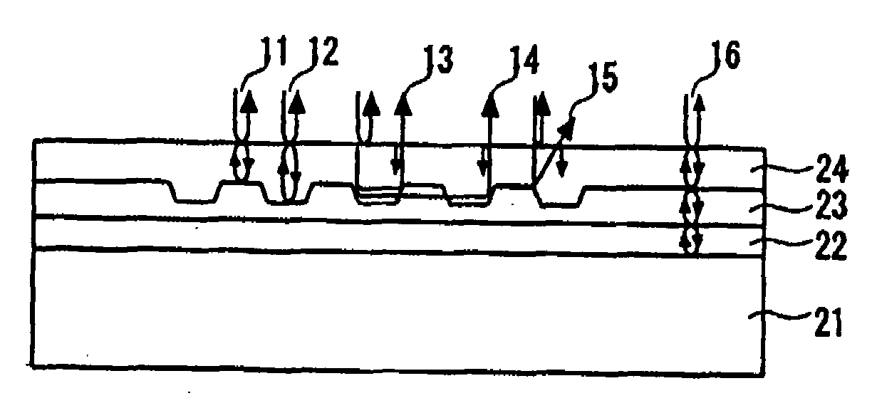
[0147]FIG. 11 is a sectional view showing a geometry of a micro-structure and reflection characteristics under irradiation with the measuring beam in Example 2 of the method of measuring a micro-structure according to the present invention. The configuration shown in FIG. 11 differs from that of Example 1, in that semiconductor layers A 22 and B 23 are formed on a semiconductor substrate 21, and the periodic micro-structure is formed on the semiconductor layer B 23.
[0148]As the reflected light obtained upon irradiation with the measuring beam, it is necessary in this Example to take:[0149]reflection at the interface between the substrate and the semiconductor layer A; and[0150]reflection at the interface between the semiconductor layer A and semiconductor layer B;
into consideration together with the reflection on the surface of the substrate, as indicated by a reflected light 16 on the flat portion of th...
example 3
[0172]Next paragraphs will detail Example 3 of the present invention, referring to the attached drawings.
[0173]As described in Example 1, the reflection spectrum obtained upon irradiation with the measuring beam onto the micro-structure is strongly affected by the geometry, and is reflected into the peak wavelength, intensity and so forth. Mathematical expression of the features (wavelength parameters) of the reflection spectrum therefore makes it possible to indicate dimension to be controlled.
[0174]FIG. 13 is a sectional view showing a geometry of a micro-structure and reflection characteristics of a measuring beam observed in a sample measurement according to Example 3 of the method of measuring a micro-structure of the present invention. The configuration shown in FIG. 13 differs from that of Example 2, in that the semiconductor layers A 22 and B 23 are formed on the semiconductor substrate 21, the periodic micro-structure is formed on the semiconductor layer B 23, and a semicon...
PUM
 Abstract
Description
Claims
Application Information
 - R&D
- Intellectual Property
- Life Sciences
- Materials
- Tech Scout
- Unparalleled Data Quality
- Higher Quality Content
- 60% Fewer Hallucinations
Browse by: Latest US Patents, China's latest patents, Technical Efficacy Thesaurus, Application Domain, Technology Topic, Popular Technical Reports.
© 2025 PatSnap. All rights reserved.Legal|Privacy policy|Modern Slavery Act Transparency Statement|Sitemap|About US| Contact US: help@patsnap.com


