Quartz crystal device

Inactive Publication Date: 2009-03-12
NIHON DEMPA KOGYO CO LTD
View PDF6 Cites 14 Cited by
  • Summary
  • Abstract
  • Description
  • Claims
  • Application Information

AI Technical Summary

Benefits of technology

[0014]An object of the present invention is to provide a quartz crystal device which is easily made compact, does not cause a trouble when a mechanical impact is applied, and easily manufactured with electrodes from a crystal blank capable of being easily led.
[0016]According to such a configuration, the crystal blank is mechanically integrated with the first container and the second container by brazing using a brazing material layer, and therefore, an adhesive does not have to be used for mechanically holding the crystal blank. Accordingly, the problem of peeling of an adhesive does not occur when a mechanical impact is applied to the quartz crystal device, and therefore, the vibration characteristic is kept favorable. The problem of a variation of the inclination of the crystal blank does not occur, and therefore, the size, especially the height of the quartz crystal device can be suppressed to be small. By using brazing, manufacture of it is facilitated, a container constituted of, for example, laminated ceramics can be used as the container, and electrodes can be easily led from the crystal blank. As the brazing material layer, for example, the one constituted of a eutectic alloy can be used.
[0019]According to the present invention, for example, a quartz crystal device which is easily made compact, does not cause a trouble when mechanical impact is applied, and is easily manufactured, with electrodes capable of being easily led from a crystal blank, is obtained.

Problems solved by technology

In the conventional crystal unit shown in FIGS. 1A and 1B, the crystal blank is fixed to the crystal holding terminals with, for example, the conductive adhesive or the like, but in such a configuration, when a mechanical impact is applied to the crystal unit, the impact which is applied to the crystal blank is directly transmitted to the conductive adhesive, and therefore, there is the fear that the conductive adhesive is torn off and peeled from the crystal holding terminals, or stress occurs to the conductive adhesive.
On the other hand, in the configuration disclosed in JP-A-9-326663, the covers are joined to the quartz crystal plate which functions as the vibration plate by direct bonding, and therefore, occurrence of a trouble due to the conductive adhesive as described above when a mechanical impact is applied to the crystal unit is prevented, but since a special joining method called direct bonding is used, there are the problems that manufacture of the crystal unit is difficult and manufacture cost increases.
Further, as the covers, only the covers made of quartz crystal or glass can be used, and therefore, there is the problem that the configuration for leading the electrodes, which are formed on the quartz crystal plate as the vibration plate, outside is complicated.

Method used


Image

  • Quartz crystal device
  • Quartz crystal device
  • Quartz crystal device

Examples


Embodiment Construction

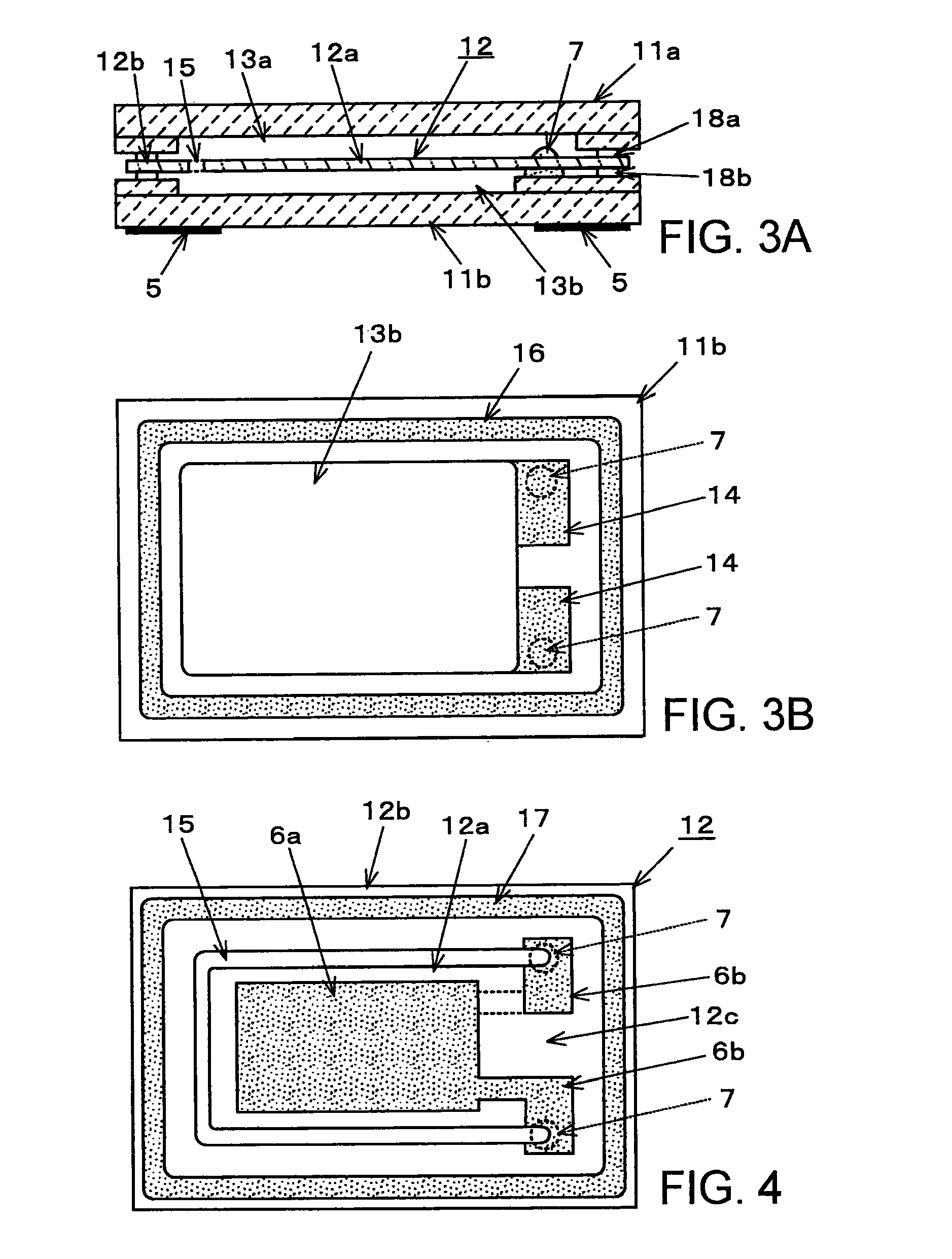
[0027]FIGS. 3A and 3B show a crystal unit which is a quartz crystal device according to one embodiment of the present invention. The crystal unit of the embodiment is configured by sandwiching quartz crystal blank 12 with upper container 11a and lower container 11b. Upper container 11a and lower container 11b have planar outer shapes substantially in rectangles in the same sizes. Each of container 11a and 11b is formed by laminated ceramics. Shallow recess 13a is formed on an undersurface illustrated in FIG. 3A of upper container 11a, and, likewise, shallow recess 13b is formed on a top surface illustrated in the drawing of lower container 11b. Recesses 13a and 13b are formed to be substantially rectangular regions so that outer perimeter parts of containers 11a and 11b are left in frame shapes and the portions other than the outer perimeter parts are recessed. A space defined by both recesses 13a and 13b becomes a space in which vibration region 12a of crystal blank 12 is held and ...


PUM


Abstract

A quartz crystal device includes: a quartz crystal blank having an outer perimeter part and a vibration region partially separated mechanically from the outer perimeter part by a cut-out groove; a first container joined to a first principal surface of the crystal blank by being joined to an entire perimeter of the perimeter part of the crystal blank via a brazing material layer in the first principal surface; and a second container joined to a second principal surface of the crystal blank by being joined to an entire perimeter of the outer perimeter part of the crystal blank via a brazing material layer in the second principal surface. The vibration region of the crystal blank is hermetically encapsulated in a space formed by the first container, the second container and the outer perimeter part of the crystal blank.

Description

BACKGROUND OF THE INVENTION[0001]1. Field of the Invention:[0002]The present invention relates to a quartz crystal device, such as a crystal unit and a crystal oscillator, having the configuration in which at least a vibration region of a quartz crystal blank is hermetically encapsulated in a container.[0003]2. Description of the Related Art:[0004]A quartz crystal unit in which a quartz crystal blank is hermetically encapsulated in a container, a crystal oscillator in which such a crystal unit and an IC (integrated circuit) chip with a circuit using the crystal unit are integrated, and the like are generically called quartz crystal devices, and are used in various kinds of electronic equipment. Above all, surface-mount quartz crystal devices each having the configuration in which a crystal blank is hermetically encapsulated in a surface-mount container are widely incorporated especially in portable electronic equipment, for example, portable telephones as reference sources for frequ...

Claims


Application Information

Patent Timeline
IPC IPC(8): H01L41/053H03B5/36
CPCH03H9/0519H03H9/0547H03H9/1035H01L2224/16225H01L2224/48091H01L2924/19105H01L2224/48227H01L2924/00014
Inventor HARIMA, HIDENORI
Owner NIHON DEMPA KOGYO CO LTD
Why Eureka
Try Eureka