
Device for a product temperature variation detection below a threshold value

Inactive Publication Date: 2020-06-18
BONOMI RENATO
View PDF7 Cites 2 Cited by
  • Summary
  • Abstract
  • Description
  • Claims
  • Application Information

AI Technical Summary

Benefits of technology

The invention relates to a device that can be easily made and applied. The device is designed to be simple and immediate to be understood by the end user, so as to avoid misunderstandings or misinterpretations. The invention also aims to increase the compliance of a possible drug in patients having difficulties. The patent describes a method to prepare passivated gold nanoparticles, which can be used in the device.

Problems solved by technology

The definition of the temperature profile over time of a product is currently difficult to implement.
This variation in the temperature of a product often leads to its alteration, which is not always visible with the naked eye.
This often leads to fraud or concealment of anomalies in a product or part of it, as well as obvious consequences of toxicity for those who use it.
The commercial success of these devices has not been relevant due to their fragility, their high cost and not small size; they can also be easily removed and manipulated.
Naturally, since these sensors serve to prevent tampering by third parties and to signal possible frauds, the possibility that this substance, subjected to such irradiation, returns to its original color, makes this system susceptible to alterations.

Method used


Image

  • Device for a product temperature variation detection below a threshold value
  • Device for a product temperature variation detection below a threshold value
  • Device for a product temperature variation detection below a threshold value

Examples


Embodiment Construction

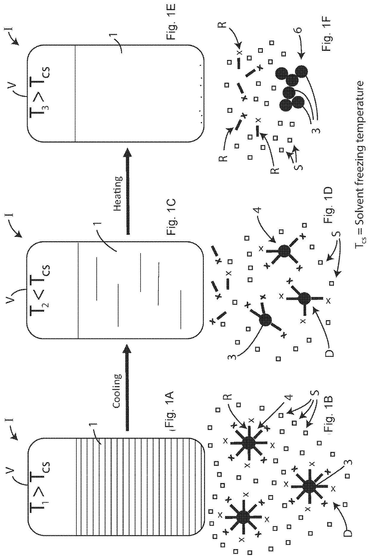
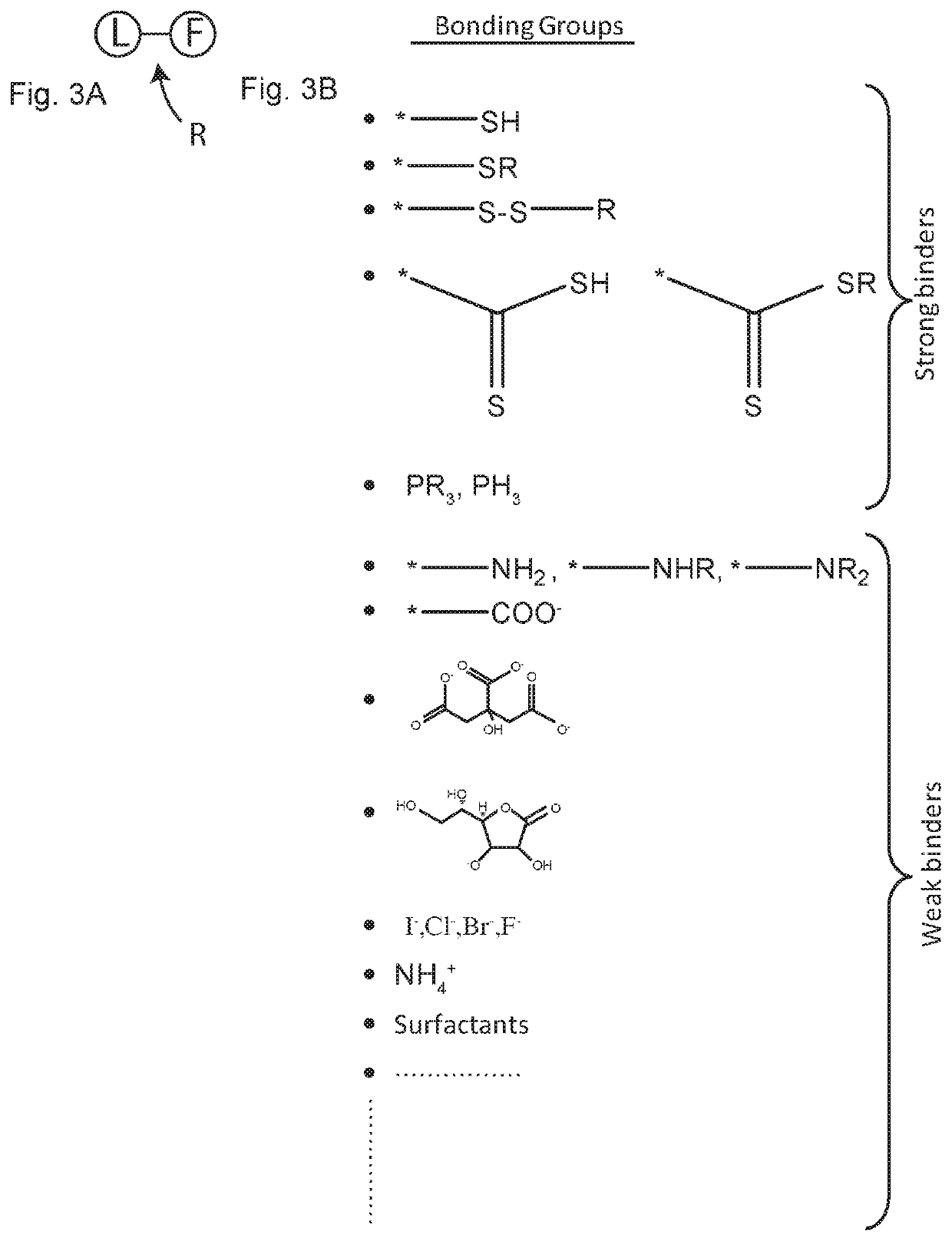
[0044]The invention consists of a system for detecting a change in temperature below a threshold, even when this change has subsequently been reversed. The system conceived makes it possible to detect whether the temperature value falls below a predetermined value. This value can be modified ad hoc, depending on the nature of the various components that make up the system; in other words, it can be modified according to the solvent (or liquid phase) S, and of the complex created by the metal nanoparticles and the coating R, hereinafter also referred to as the solid phase D.

[0045]The idea is based on the phenomenon of aggregation of metallic nanoparticles, following the freezing of the solvent in which they are dispersed.

[0046]The phenomenon is irreversible, due to the breakdown of the structure of the nanoparticle and of the subsequent precipitation of aggregates no longer dispersible in the solvent. Self-assembly is a molecular phenomenon through which a complex molecular system is...


PUM


Abstract

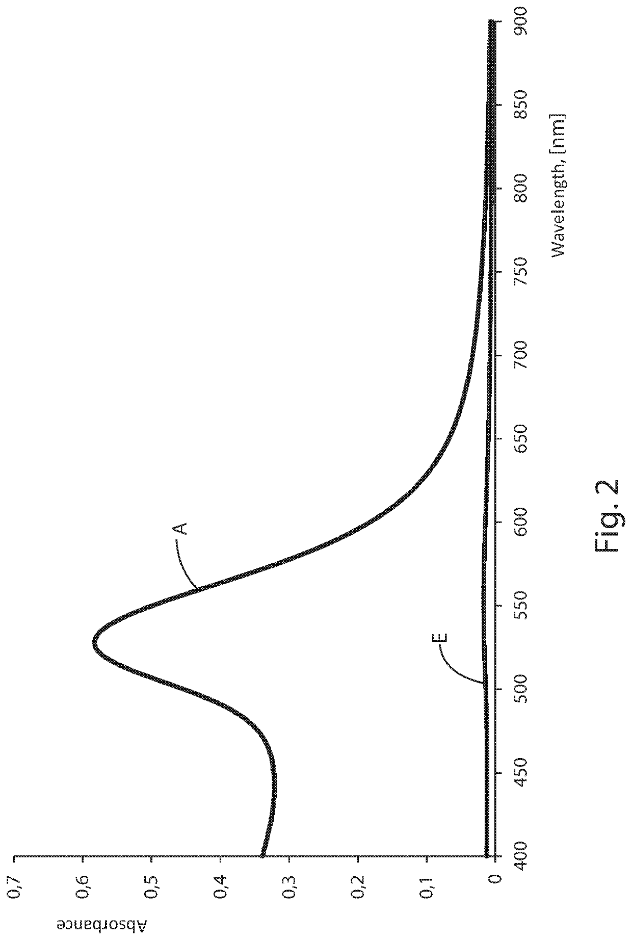
The present invention relates to a device for monitoring a temperature variation undergone by a product, which detects a drop in temperature below a predetermined temperature threshold (Tcs), comprising: a sealed casing (I) which defines a containment space (V), and a mixture contained, or containable, in said containment compartment (V) which comprises a liquid phase (S) and a solid (D) comprising metal particles having an average nanometric size comprised between 1 and 300 nm and a coating layer (R) of said particles. This coating (R) comprises an organic material and is configured in such a way that, in a configuration of use of the device at a first temperature (T1) greater than said threshold temperature (Tcs), it allows the maintenance of the solid (D) in solution in said liquid phase (S), in which the particles are separated from each other, while at a crystallization temperature (T2) of said liquid phase (S), being said temperature (T2) equal to or lower than said threshold temperature (Tcs), the coating layer (R) separates from the metal particles allowing an aggregation of the metal particles. The mixture undergoes an irreversible loss of optical properties, allowing the detection of undesired temperature variation.

Description

RELATED APPLICATION[0001]This application claims the benefit of priority of Italian Patent Application No. 102018000011174 filed on Dec. 17, 2018, the contents of which are incorporated herein by reference in their entirety.FIELD AND BACKGROUND OF THE INVENTION[0002]The present invention is in the field of sensors for detecting temperature variations, and in particular refers to a sensor that detects temperature drops below a predetermined threshold.[0003]The definition of the temperature profile over time of a product is currently difficult to implement. Especially in the pharmaceutical and food sectors, there are products that deteriorate when subjected to an excessive lowering of the temperature, even if subsequently brought back to an ideal temperature.[0004]This variation in the temperature of a product often leads to its alteration, which is not always visible with the naked eye. This often leads to fraud or concealment of anomalies in a product or part of it, as well as obvio...

Claims


Application Information

Patent Timeline
IPC IPC(8): G01N31/22G01K11/06B82Y15/00
CPCG01K11/06G01N31/229B82Y15/00G01K11/12G01K3/04G01K2211/00G01N25/00G01N33/20
Inventor BONOMI, RENATO
Owner BONOMI RENATO
Learn More