
Fuel injection control device

a control device and fuel injection technology, applied in the direction of electrical control, process and machine control, instruments, etc., can solve the problems of not being realistic for the present production system, affecting the efficiency of production, and individual differences in characteristics, so as to and reduce the pulsation of fuel

Active Publication Date: 2009-03-05
DENSO CORP
View PDF6 Cites 36 Cited by
  • Summary
  • Abstract
  • Description
  • Claims
  • Application Information

AI Technical Summary

Benefits of technology

[0011]The inventors invented the above-described device by paying an attention to a phenomenon that injection characteristics (output torque, emission characteristics and the like of a target engine) changes if a geometric centroid (hereinafter, referred to as an injection centroid) of a diagram as a profile of an injection rate transition differs even when the injection is performed with the same injection quantity. That is, with this device, the injection centroid of the diagram as the present profile of the injection rate transition can be detected with the injection centroid detecting section. Also, the injection command to the target injector or the injection condition of the injector can be varied with the injection varying section such that a relative positional relationship between the injection centroid of the diagram as the actual profile of the injection rate transition and the injection centroid of the basic diagram becomes a predetermined relationship in the same combustion cycle or in a subsequent combustion cycle. With such the construction, the injection command, the injection condition, and eventually the position of the injection centroid is adjusted in accordance with the injection characteristic of each time, thereby enabling appropriate fuel injection control.
[0048]The pressure fluctuation mode due to the injection (including the injection operation) can be sensed through the sensor output of the pressure sensor at higher accuracy as the installation position of the fuel pressure sensor is closer to the fuel injection hole of the injector. Therefore, in order to sense the pressure fluctuation mode with high accuracy, it is effective to install the fuel pressure sensor inside or near the injector as in the construction according to the above aspect. In this case, if at least one of the fuel pressure sensors is provided in a fuel inlet of the injector, mountability and maintenance performance of the fuel pressure sensor are improved and the pressure can be sensed with high accuracy in a comparatively stable manner.

Problems solved by technology

However, when mass production and mass marketing of respective components of the engine control system are performed, usually, there occur certain individual differences in characteristics of various kinds of control components including the injector, for example, between the engines and also between the cylinders in the case of a multi-cylinder engine.
In such the case, it takes a lot of works and is not realistic for the present production system to obtain the adaptation values (the optimum injection patterns) for all the components (for example, all the cylinders manufactured through the mass production and mounted in the vehicle) in consideration of also the individual differences.
Therefore, it is difficult to perform the control in consideration of all the influences due to the individual differences even when the map, in which the adaptation values are written, or the mathematical expression is used.
Even if the conventional device such as the device described in Patent document 1 can obtain the optimum value with high accuracy in an initial stage, an influence of the subsequent characteristic change is unknowable.
Therefore, there is a concern that there occurs a deviation from the optimum value with passage of time.
Therefore, it is difficult to thoroughly remove the influence.

Method used


Image

  • Fuel injection control device
  • Fuel injection control device
  • Fuel injection control device

Examples


Embodiment Construction

[0076]Hereafter, a fuel injection control device according to an embodiment of the present invention will be described with reference to the drawings. The control device according to the present embodiment is mounted, for example, in a common rail fuel injection system (high-pressure injection fuel supply system) for a diesel engine. That is, like the device described in Patent document 1, the control device according to the present embodiment is used for performing injection supply (direct injection supply) of high-pressure fuel (for example, light oil at injection pressure of 1000 atmospheres or higher) directly into a combustion chamber in a cylinder of a diesel engine.

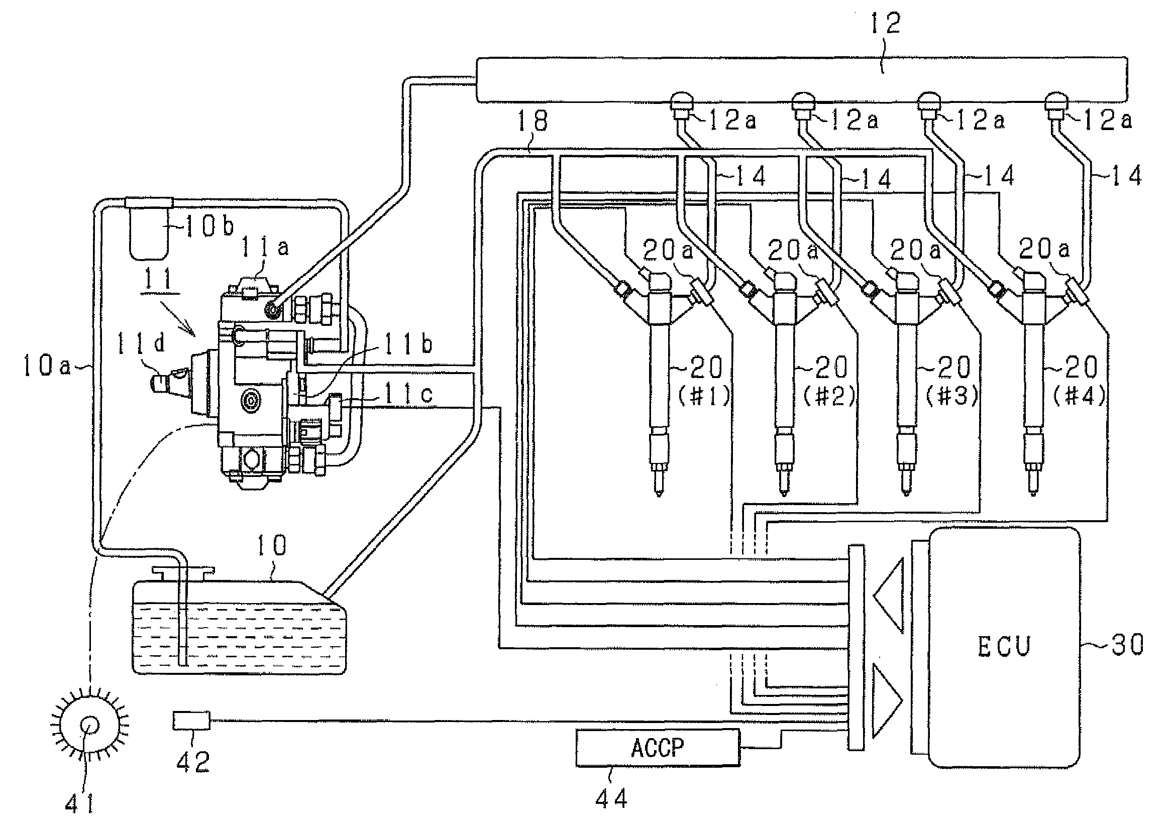
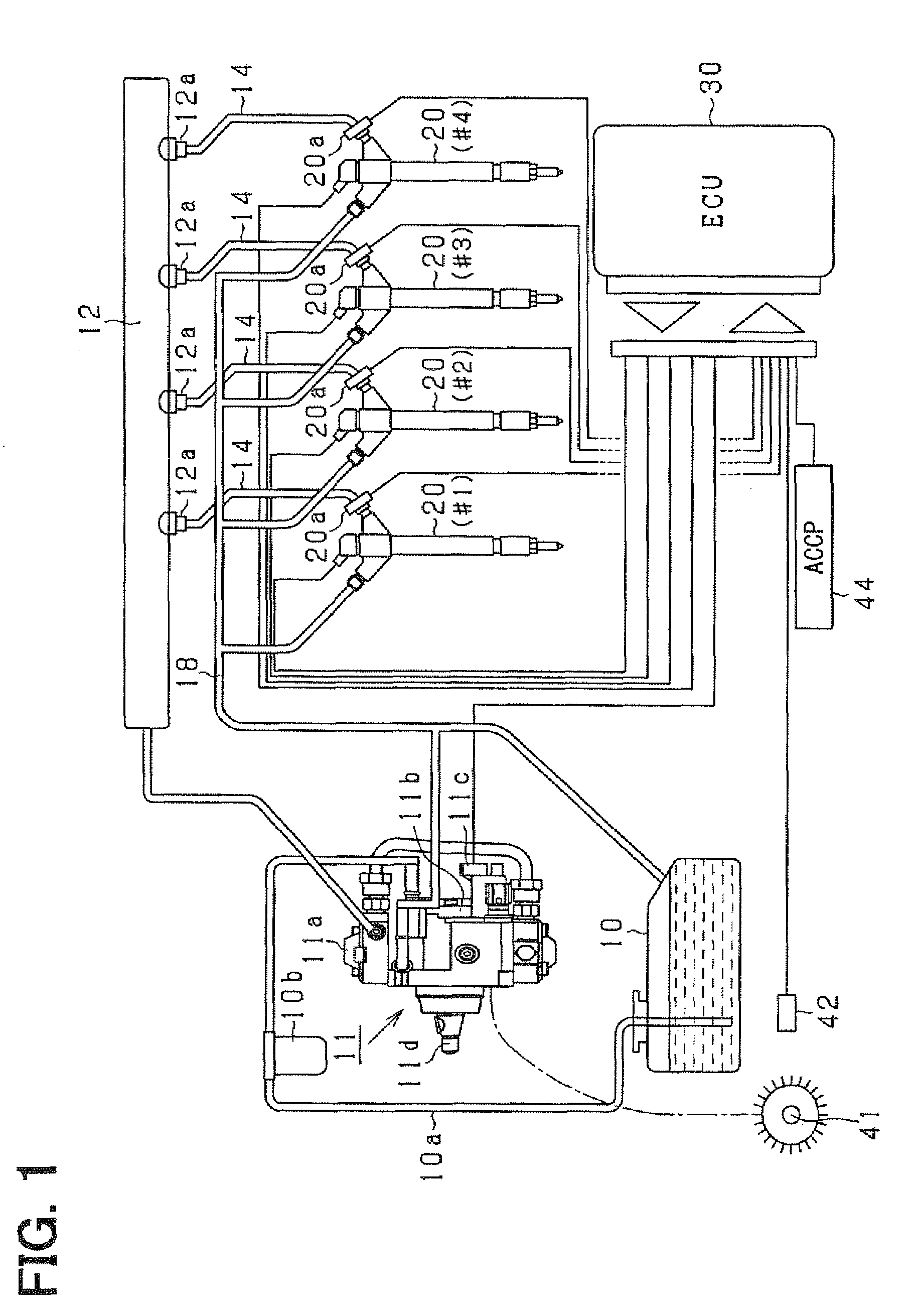
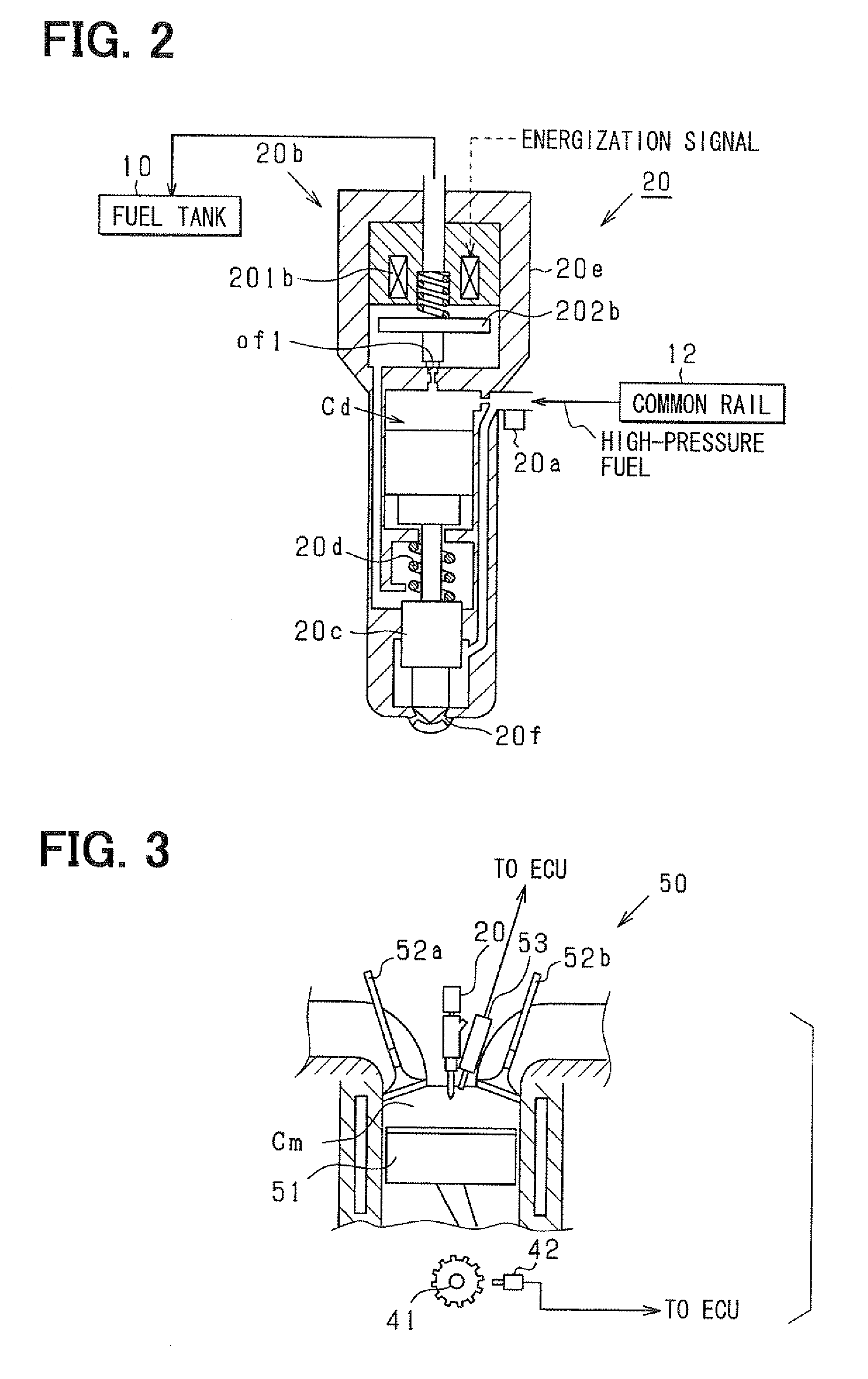
[0077]First, an outline of the common rail fuel injection control system (an in-vehicle engine system) according to the present embodiment will be explained with reference to FIG. 1. It is assumed that the engine according to the present embodiment is a multi-cylinder engine (for example, an in-line four-cylinder e...


PUM


Abstract

A fuel injection control device (ECU) for controlling injection supply of fuel to a target engine has a program for sequentially sensing fuel pressure fluctuating with injection of a predetermined injector a program for detecting an injection centroid of a diagram as a profile of a transition of an injection rate of the injector at a present time based on a transition of the sequentially sensed fuel pressure, and a program for varying an injection command (injection timing) of the injector based on the detected injection centroid and an injection centroid of a predetermined basic diagram such that a relative positional relationship between the injection centroids of the diagram as the actual profile of the injection rate transition and the basic diagram becomes a relationship, in which timings of the injection centroids are close to each other.

Description

CROSS REFERENCE TO RELATED APPLICATION[0001]This application is based on and incorporates herein by reference Japanese Patent Application No. 2007-227121 filed on Aug. 31, 2007.BACKGROUND OF THE INVENTION[0002]1. Field of the Invention[0003]The present invention relates to a fuel injection control device that is applied to a fuel supply system injecting fuel through a predetermined injector and that controls a fuel injection characteristic of the system.[0004]2. Description of Related Art[0005]As one of technologies for improving emission of an in-vehicle diesel engine or the like, there is a known technology (high-pressure injection) for injecting and supplying fuel, which is pressurized to high pressure, directly into a cylinder through an injector. In recent years, a common rail fuel injection system (for example, a system described in Patent document 1: JP-A-H10-220272) has come to attract attention as a fuel injection system realizing the high-pressure injection. In the system,...

Claims


Application Information

Patent Timeline
Patent Type & Authority Applications(United States)
IPC IPC(8): F02D41/30
CPCF02D35/028F02D41/2467F02D41/3809F02D41/40Y02T10/44F02D2200/0602F02D2250/04F02M2200/24F02D41/401Y02T10/40
Inventor NAKATA, KENICHIROISHIZUKA, KOJI
Owner DENSO CORP
Learn More