
Tourniquet and method of use

a technology of tourniquets and stents, which is applied in the field of new tourniquet devices, can solve the problems of high shearing stress, loss of blood, and unnecessary injury

Active Publication Date: 2009-03-05
PHIL DURANGO
View PDF49 Cites 44 Cited by
  • Summary
  • Abstract
  • Description
  • Claims
  • Application Information

AI Technical Summary

Benefits of technology

"The present invention is a tourniquet that can be used to restrict the flow of blood in a body part. It consists of an outer sleeve, a buckle, an inner strap, and a windlass. The windlass applies tension to the inner strap, which in turn applies a compressive force to the body part, preventing blood flow. The buckle has a top and bottom, with first and second lateral sides that are spaced apart from each other. It also includes an intermediate bar with top and bottom surfaces with sidewalls between them. The buckle has a first port and a second port with at least one tooth extending into each port. The tourniquet can be easily attached to the body part and operated to restrict blood flow."

Problems solved by technology

Loss of blood is a major cause of death in emergency situations in which the injured person is alone or medical assistance is not immediately available.
This tends to draw soft tissues underlying the strap into the ratchet or buckle device, pinching the soft tissue and creating a region of very high localized pressure which will cause unnecessary injury.
This effect may also create high shearing stresses in the underlying soft tissues, increasing the probability of nerve and tissue injury.
In general, the application of uneven or non-uniform application of pressure around the limb leads to the need for unnecessarily high overall tourniquet pressures to reliably and predictably stop arterial blood flow, and this need for unnecessarily high pressure increases the probability of a range of unnecessary injuries to nerves, muscles and the limb.

Method used


Image

  • Tourniquet and method of use
  • Tourniquet and method of use
  • Tourniquet and method of use

Examples


Embodiment Construction

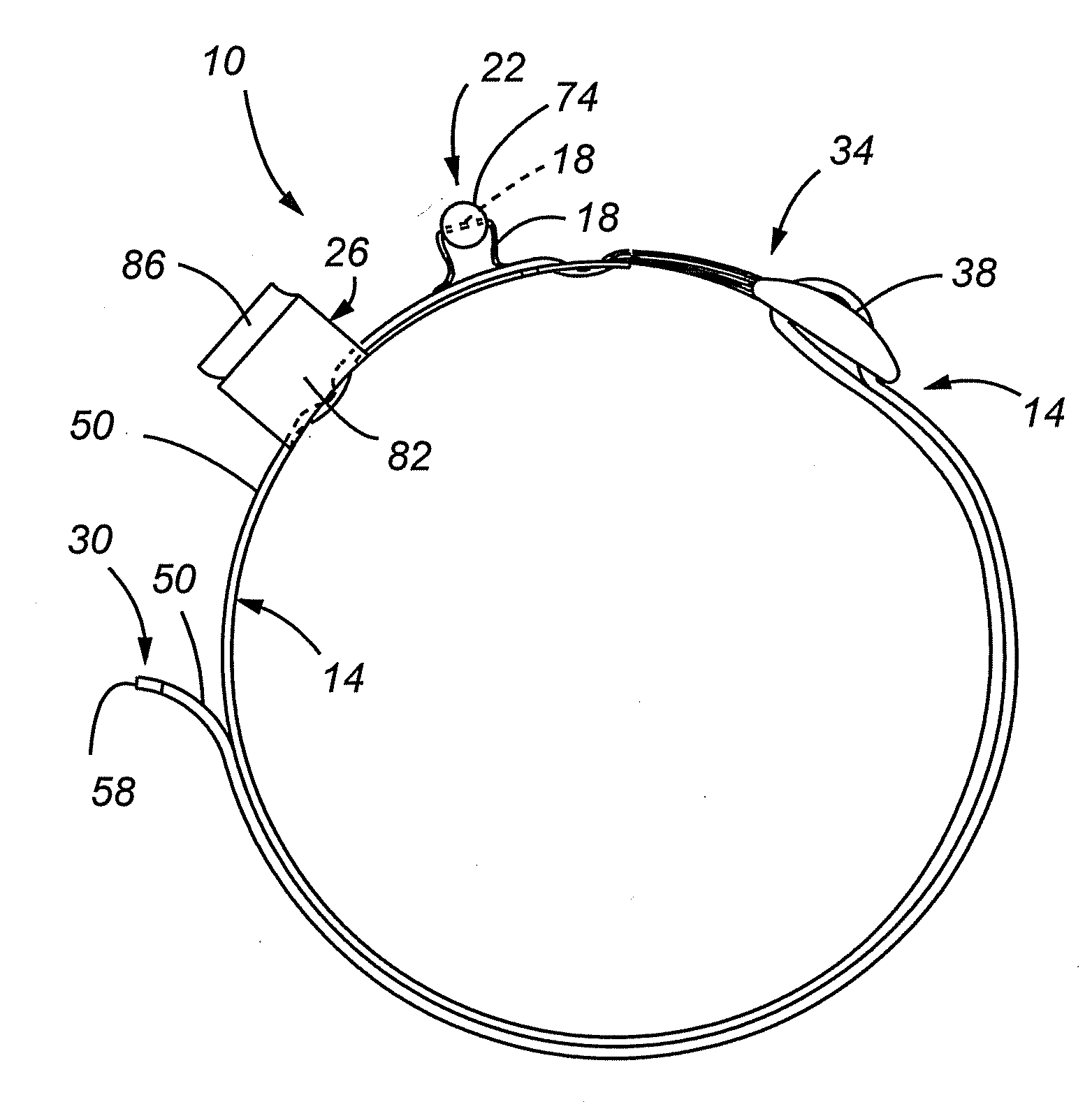
[0043]The present invention comprises a tourniquet that can be manipulated and tightened by the user, including the victim, using one hand, if necessary. In addition, the tourniquet provides improved circulation stoppage by way of an inner tightening strap positioned within a sleeve.

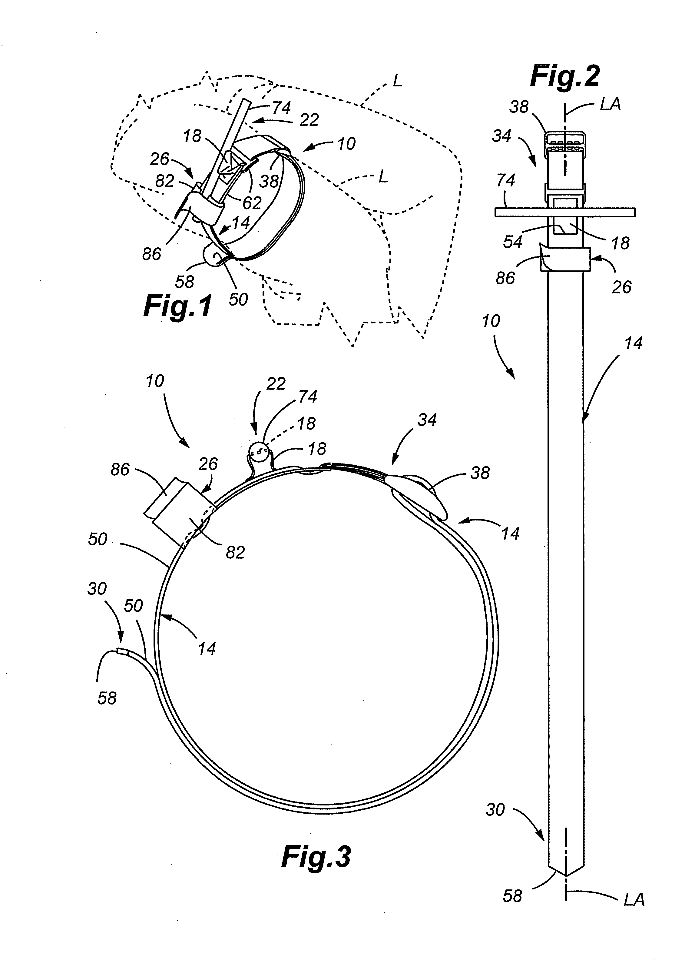
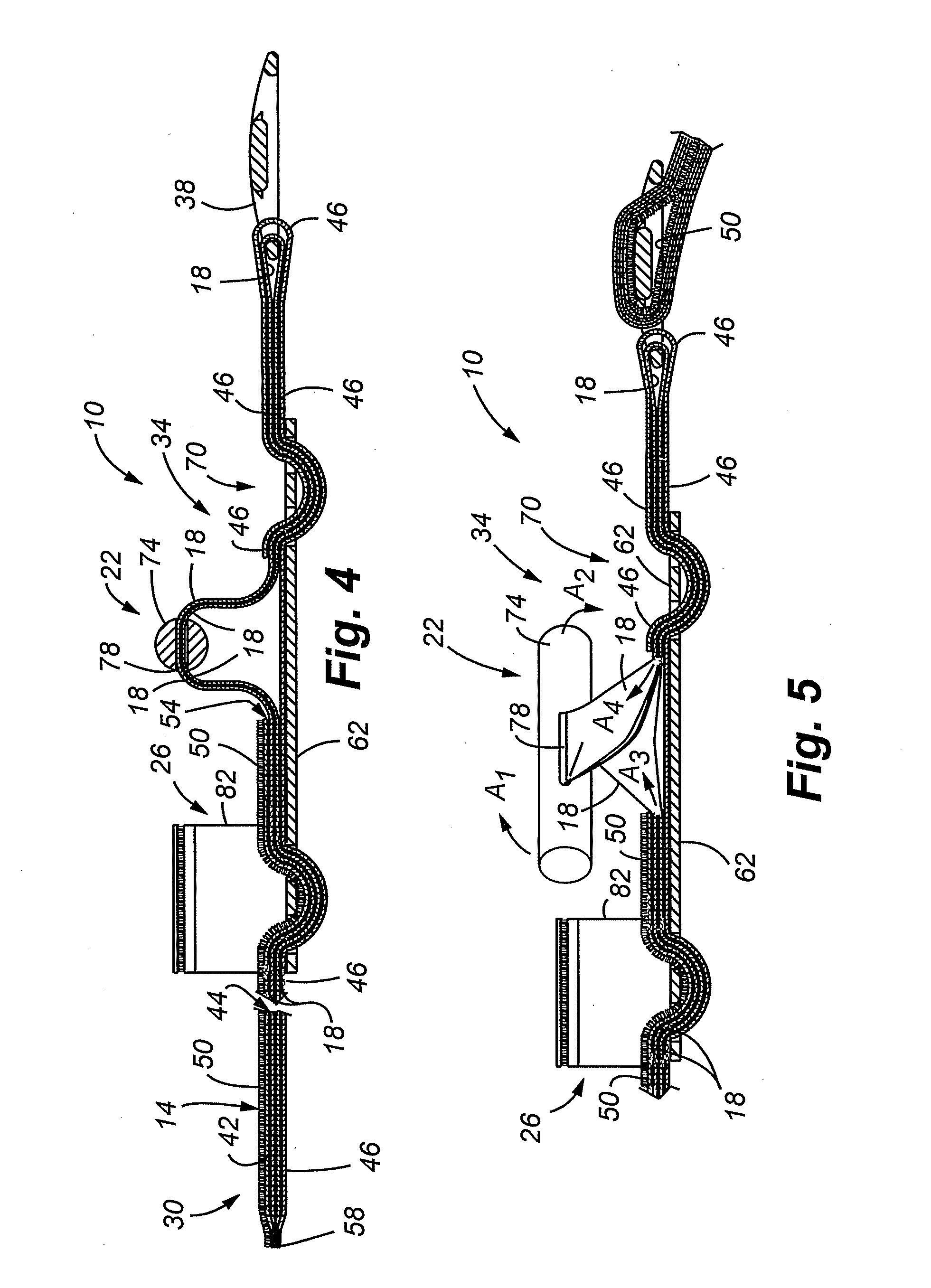
[0044]Referring now to FIG. 1, a tourniquet 10 in accordance with embodiments of the present invention is shown. The tourniquet 10 comprises a first elongated member or an outer sleeve 14, a second elongated member, inner tightening member or inner strap 18, a tightening mechanism 22 and a securing mechanism 26. As shown in FIG. 1, the tourniquet 10 can be applied to an appendage, as for example, leg L, and then tightened to restrict the flow of blood to the leg L.

[0045]Referring now to FIG. 2, the tourniquet 10 is shown prior to use, or in a stretched-out orientation. The outer sleeve 14 comprises a longitudinally extensive material having a first end 30 and a second end 34. In accordance with embodimen...


PUM


Abstract

A tourniquet for restricting a flow of blood in a body part comprises a first elongated member, and a second elongated member in slidable engagement with the first elongated member. In addition, the tourniquet includes a tensioning mechanism connected to the second elongated member, wherein a compressive force is applied to the body part upon applying a tensile force to the second elongated member using the tensioning mechanism. At least one embodiment of the present invention comprises a buckle having one or more of a raised intermediate bar and one or more teeth for contacting a portion of the first elongated member. The tourniquet is suited for emergency use, and may be applied by using only one hand. Thus, the tourniquet may be applied, manipulated and tightened by the wearer, even if the wearer is limited to the use of a single hand.

Description

CROSS REFERENCE TO APPLICATION[0001]The present application cross references, but does not claim priority to U.S. patent application Ser. No. 11,147,806 entitled “Tourniquet and Method of Use” filed on Jun. 6, 2005, the entire disclosure of which is incorporated herein by reference in its entirety.FIELD[0002]The present invention relates to a novel flow restriction device, and more particularly, to a novel tourniquet device for restricting the flow of blood.BACKGROUND[0003]The following text should not be construed as an admission of knowledge in the prior art. Furthermore, citation or identification of any document in this application is not an admission that such document is available as prior art to the present invention, or that any reference forms a part of the common general knowledge in the art.[0004]Loss of blood is a major cause of death in emergency situations in which the injured person is alone or medical assistance is not immediately available. The use of a tourniquet t...

Claims


Application Information

Patent Timeline
Patent Type & Authority Applications(United States)
IPC IPC(8): A61B17/00
CPCA61B17/1327
Inventor ESPOSITO, MARKBENNETT, JONATHAN
Owner PHIL DURANGO
Learn More