
Apparatus and Method for Providing Weather and Other Alerts

a technology of alerts and alerts, applied in the field of alert systems, can solve problems such as inability to be easily deactivated by users

Inactive Publication Date: 2009-03-05
AT&T DELAWARE INTPROP INC
View PDF58 Cites 22 Cited by
  • Summary
  • Abstract
  • Description
  • Claims
  • Application Information

AI Technical Summary

Benefits of technology

[0012]Briefly described, the present invention comprises an alert apparatus and method for receiving a location-specific alert (i.e., an alert directed and relevant to a particular geographical area) and for informing a user, who may be visually or hearing impaired, of the existence and severity of the alert. More particularly, the present invention includes an alert apparatus and method which allow a user to receive data corresponding to an alert which has been broadcast via particular transmitters operating within a cellular, PCS, or wireless telephone communications network, thereby allowing receipt of a location-specific alert (and a textual message associated with the alert) without requiring the user to input, to the alert apparatus, data representative of or identifying the location of the apparatus. Further, the present invention includes an alert apparatus and method which produces high-decibel level audible sounds and high-intensity flashing strobe light corresponding to alerts of the most severe level and which produces low-decibel level audible sounds and low-intensity flashing light from a light-emitting diode corresponding to alerts of a less severe level.

Problems solved by technology

Furthermore, in the embodiment, the alert device operates continuously when supplied with electrical power, has no on / off switch, and thus cannot easily be deactivated by a user unlike a cellular or PCS telephone handset.

Method used


Image

  • Apparatus and Method for Providing Weather and Other Alerts
  • Apparatus and Method for Providing Weather and Other Alerts
  • Apparatus and Method for Providing Weather and Other Alerts

Examples


Embodiment Construction

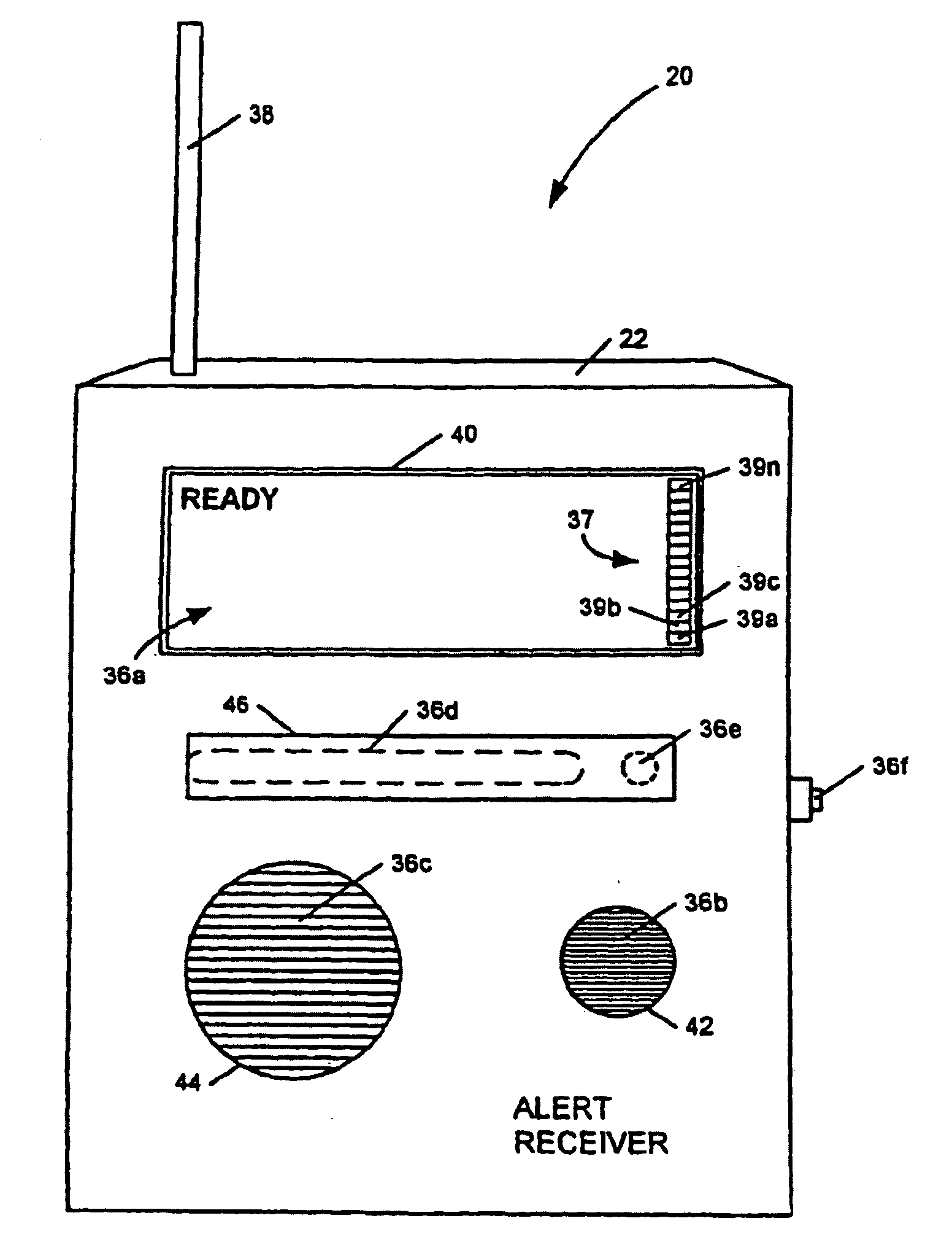
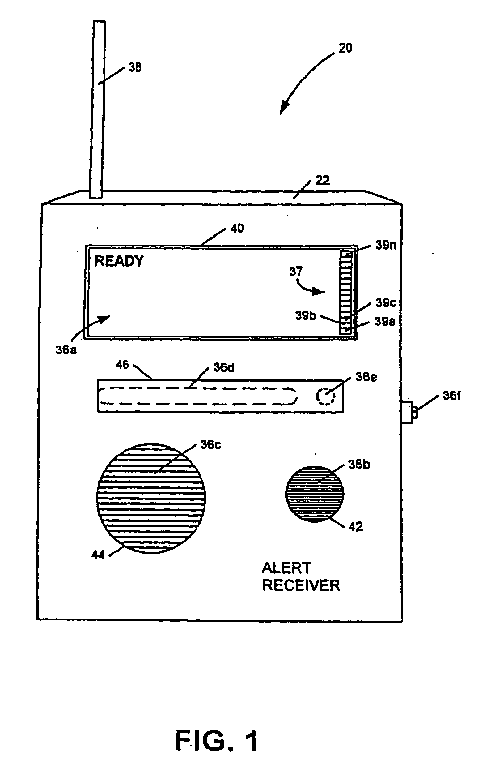
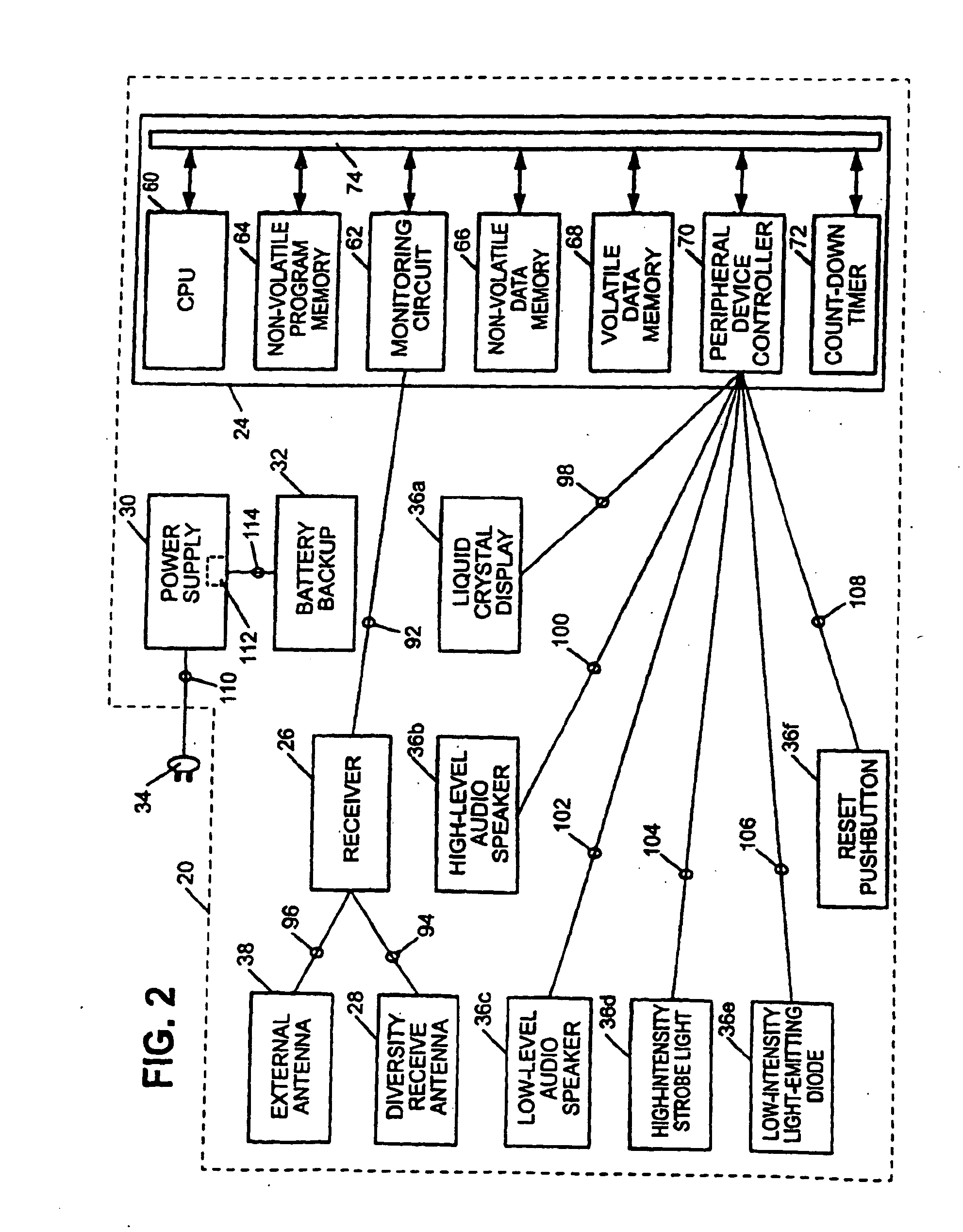
[0049]Referring now to the drawings, in which like numerals represent like components throughout the several views, an alert device 20, in accordance with an apparatus of an embodiment of the present invention, is shown in pictorial form in FIG. 1 and in block diagram form in FIG. 2. The alert device 20 comprises an enclosure 22 and a microcomputer 24, receiver 26, diversity receive antenna 28, power supply 30, and backup battery 32 residing therein. Preferably, the enclosure 22 is manufactured from a durable plastic material and the alert device 20 is directly pluggable into an electrical wall outlet through use of an electrical plug 34 located on the back of the enclosure 22, thereby avoiding the need for mounting hardware and the difficulties of mounting the enclosure to a wall. According to the apparatus of an embodiment, the receiver 26 is adapted to receive digital signals within the ranges of channels utilized for cellular, PCS, or other wireless communications in the area in...


PUM


Abstract

An apparatus for providing location-specific alert information associated with an alert condition relevant to a geographical area may include a receiver adapted to receive transmissions comprising formatted text on a communication channel of a wireless bi-directional communication network; a peripheral device operable to indicate an alert condition, including displaying the formatted text; and a controller communicatively coupled to the receiver and the peripheral device. The controller is operable to monitor a communication channel of the network for the receipt of a transmission of location-specific alert information from a transmitter servicing a geographical area and to operate the peripheral device in response to the reception of the transmission of the location-specific alert information to display the formatted text. The location-specific alert information is broadcast within the geographical area by at least one transmitter of the wireless bi-directional communication network having communication channels and transmitters which are each positioned to provide communication services to specific geographical areas serviced by the communication network.

Description

CROSS REFERENCE TO RELATED APPLICATIONS[0001]This patent application is a continuation-in-part of U.S. patent application Ser. No. 10 / 449,284 filed on May 30, 2003, which is a continuation-in-part of U.S. patent application Ser. No. 10 / 016,307 filed on Dec. 10, 2001, which is a continuation-in-part of U.S. patent application Ser. No. 09 / 330,667 filed on Jun. 11, 1999 and issued as U.S. Pat. No. 6,329,904. This application also claims the benefit of the filing date of U.S. Pat. No. 6,329,904.FIELD OF THE INVENTION[0002]This invention relates generally to the field of alert systems and, in its embodiments, to alert systems utilizing cellular, personal communication system, or wireless telecommunication technology to deliver an alert to an alert device.BACKGROUND OF THE INVENTION[0003]In recent decades, the science of meteorology has advanced rapidly, allowing increasingly accurate detection and prediction of severe and hazardous weather. Specifically, Doppler radar systems and high-re...

Claims


Application Information

Patent Timeline
Patent Type & Authority Applications(United States)
IPC IPC(8): G01W1/00G08B27/00
CPCG08B27/006G01W1/00Y02A90/10
Inventor LAMB, GEORGE W.
Owner AT&T DELAWARE INTPROP INC
Learn More