
Method of plasma particle simulation, storage medium, plasma particle simulator and plasma processing apparatus

a plasma particle and simulation technology, applied in plasma techniques, separation processes, nuclear engineering, etc., can solve the problems of large number of plasma particles contained in the housing chamber, poor observation accuracy, and large simulation time, so as to prevent the divergence of solutions

Active Publication Date: 2009-03-05
TOKYO ELECTRON LTD
View PDF7 Cites 3 Cited by
  • Summary
  • Abstract
  • Description
  • Claims
  • Application Information

AI Technical Summary

Benefits of technology

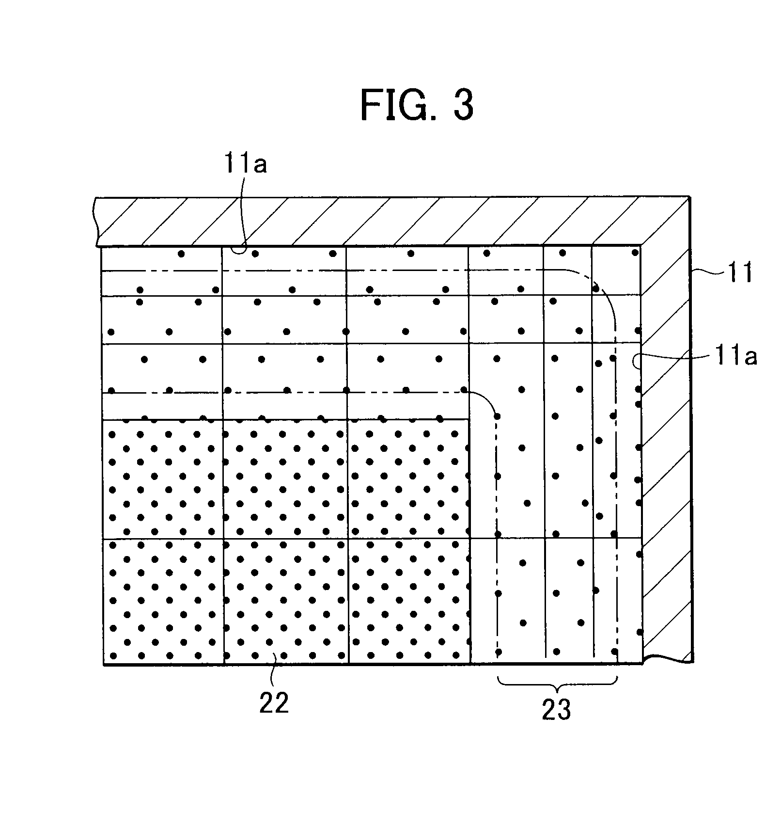
[0015]According to a first aspect of the present invention, a weighting factor corresponding to the number of plasma particles represented by a superparticle becomes smaller as the divided cell in which the weighting factor is set is located closer to a solid wall surface of an housing chamber. Consequently, it is possible to maintain the number of superparticles in the divided cell which is located near the solid wall surface and, therefore, contains a small number of plasma particles, and prevent a statistical error from becoming large in behavior calculation, thereby preventing solution divergence and improving solution accuracy.
[0017]According to the first aspect of the present invention, since plasma particles are default-set in each divided cell, it is possible to rapidly converge behavior calculations and improve solution accuracy further.
[0019]According to the first aspect of the present invention, since one of weighting functions is selected on the basis of the state of plasma predicted to be produced within the housing chamber and a weighting factor is set in each divided cell using the selected weighting function, it is possible to maintain an appropriate number of superparticles in each cell according to the plasma state, thereby reliably preventing solution divergence. In addition, it is possible to improve solution accuracy further.
[0021]According to the first aspect of the present invention, the weighting function is based on a trigonometric function. Since the value of a trigonometric function changes drastically, the value of the weighting factor in the weighting function can be varied over three or more orders of magnitude according to a distance from the solid wall surface. Consequently, it is possible to maintain an appropriate number of superparticles in each cell even in the case of a plasma state in which the number of plasma particles changes drastically over as much as three or more orders of magnitude in a sheath, thereby even more reliably preventing solution divergence. In addition, it is possible to reliably improve solution accuracy.
[0023]According to the first aspect of the present invention, an increase / decrease in the number of superparticles is determined using a probabilistic measure when superparticles move from one cell to an adjacent cell. Consequently, it is possible to appropriately achieve the cell-to-cell move of superparticles even if the weighting factors of mutually adjacent cells differ, thereby smoothly performing behavior calculations.
[0025]According to the first aspect of the present invention, a smaller weighting factor is set in the divided cell located closer to the central axis of the housing chamber, among a plurality of cells into which the space within the housing chamber specified as taking on a cylindrical shape in superparticle behavior calculation has been divided axisymmetrically with respect to the central axis. Consequently, it is possible to maintain an appropriate number of superparticles even in the divided cell which is located closer to the central axis and, therefore, contains a smaller number of plasma particles, thereby preventing solution divergence.

Problems solved by technology

Since being based on optical methodology, the aforementioned method has many factors of disturbance and, hence, a poor accuracy of observation.
On the other hand, the number of plasma particles contained in the housing chamber is enormous.
Consequently, performing a behavior calculation for each of plasma particles requires an enormous computational load, thus taking a vast amount of time for simulation.
On the other hand, the Monte Carlo method has the problem that a statistical error in calculations becomes larger as the number of superparticles decreases.
As described above, the number of superparticles subject to behavior calculation also decreases in the cell near the solid wall surface and, therefore, a statistical error in behavior calculation becomes large.
As a result, it is no longer possible to ensure consistency with the results of behavior calculation of superparticles in the portion (bulk) of plasma other than the sheath, possibly causing a solution to diverge in plasma particle simulation.

Method used


Image

  • Method of plasma particle simulation, storage medium, plasma particle simulator and plasma processing apparatus
  • Method of plasma particle simulation, storage medium, plasma particle simulator and plasma processing apparatus
  • Method of plasma particle simulation, storage medium, plasma particle simulator and plasma processing apparatus

Examples


first embodiment

[0041]First, an explanation will be made of a method of plasma particle simulation according to the present invention.

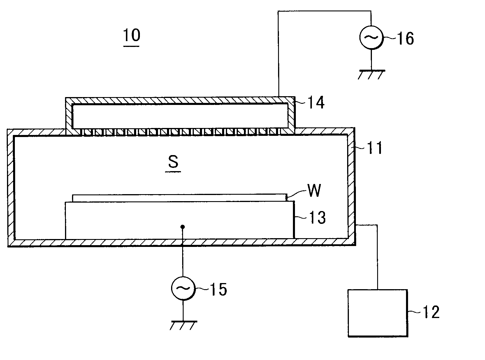
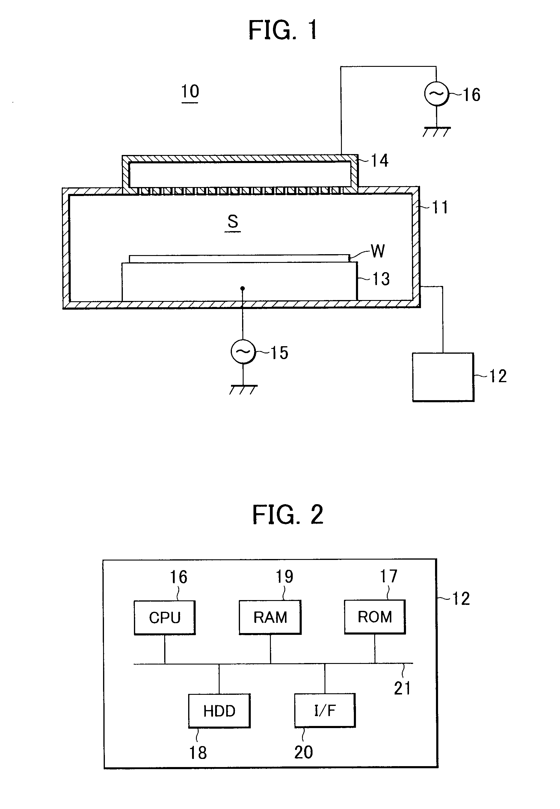
[0042]FIG. 1 is a cross-sectional view schematically illustrating a configuration of a plasma processing apparatus to which a method of plasma particle simulation according to the present embodiment.

[0043]In FIG. 1, a plasma processing apparatus 10 includes a housing chamber (chamber) 11 for housing a wafer W and a simulator 12 for performing plasma particle distribution prediction processing as a later-described method of plasma particle simulation.

[0044]The chamber 11 includes a susceptor 13 functioning as the mounting stage of the wafer W and disposed downwardly within the chamber 11, and a showerhead 14 disposed above the chamber 11 to supply a processing gas into the chamber 11. Since a radio-frequency power source 15 is connected to the susceptor 13, the susceptor 13 functions as a lower electrode for applying radio-frequency power to a space (hereinafter refer...

second embodiment

[0083]Next, an explanation will be made of a method of plasma particle simulation according to the present invention.

[0084]The present embodiment is basically the same in constitution and operation as the above-described first embodiment. Therefore, the same parts of the constitution and operation will not be described again, but only the different parts thereof will be described hereinafter.

[0085]FIG. 8 is a top view illustrating a part of a simulation model corresponding to a processing space set in implementation of a method of plasma particle simulation according to the present embodiment.

[0086]In FIG. 8, a simulation model is divided axisymmetrically with respect to the central axis of a chamber 11 into a plurality of cells. At this time, the volumes of cells near the central axis become small. Since the density of plasma particles 22 is constant in a portion corresponding to the bulk of plasma (portion including the vicinity of the central axis), the number of plasma particles...


PUM


Abstract

A method of plasma particle simulation capable of preventing solution divergence. A space within a housing chamber of a plasma processing apparatus is divided into a plurality of cells. A weighting factor corresponding to the number of plasma particles represented by a superparticle is set in each of the divided cells. Superparticles are set in each of the divided cells using plasma particles contained in the divided cell and the set weighting factor. The behavior of the superparticles in each of the divided cells is calculated. The weighting factor becomes smaller as the divided cell is located closer to a solid wall surface of the housing chamber.

Description

BACKGROUND OF THE INVENTION[0001]1. Field of the Invention[0002]The present invention relates to a method of plasma particle simulation, a storage medium, a plasma particle simulator and a plasma processing apparatus, and more particularly, to a method of plasma particle simulation for plasma with a sheath.[0003]2. Description of the Related Art[0004]A plasma processing apparatus for subjecting a plasma processing to a wafer or the like using plasma includes a housing chamber for housing the wafer. Within the housing chamber, there is generated plasma. Since a plasma distribution has a significant effect on the uniformity of processing subject to the wafer, many attempts have been heretofore made in order to know the distribution of plasma within the housing chamber.[0005]As a method for directly observing the plasma distribution, there is known a method for observing a state of light emission within the housing chamber. Since being based on optical methodology, the aforementioned m...

Claims


Application Information

Patent Timeline
Patent Type & Authority Applications(United States)
IPC IPC(8): G21G4/00
CPCH01J37/32871H05H1/46H01J37/32935
Inventor DENPOH, KAZUKI
Owner TOKYO ELECTRON LTD
Learn More