
Steering apparatus

a steering device and actuator technology, applied in the direction of steering linkages, electrical steering, transportation and packaging, etc., can solve the problems of affecting the operation the drive motor itself, and the installation of the steering actuator on the outside end of the suspension-system control arm, so as to improve the layout flexibility and saleability of the steering actuator, and achieve the effect of sacrificing riding comfor

Active Publication Date: 2009-03-05
HITACHI ASTEMO LTD
View PDF7 Cites 42 Cited by
  • Summary
  • Abstract
  • Description
  • Claims
  • Application Information

AI Technical Summary

Benefits of technology

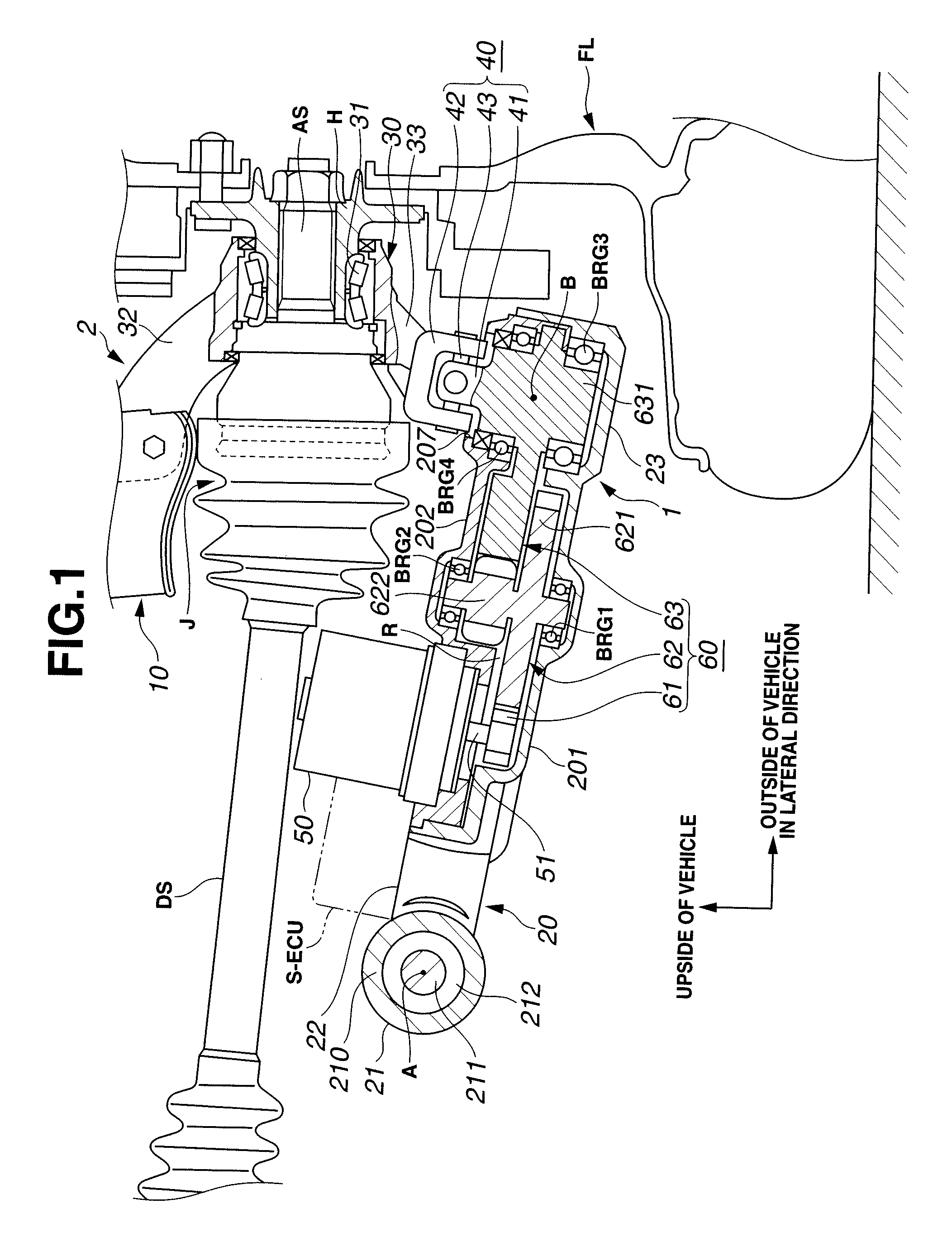
[0007]It is, therefore, in view of the previously-described disadvantages of the prior art, an object of the invention to provide a steering apparatus configured to enhance its layout flexibility and saleability, without sacrificing riding comfort.

Problems solved by technology

However, in such a case, the direct-drive motor itself must be large-sized to produce a required torque.
Therefore, practically, it is very difficult to install the steering actuator, having the specified size and weight based on the required torque, on the outside end of the suspension-system control arm coaxially with the kingpin axis, while avoiding undesired interference with road-wheel side component parts, for example, a hub carrier or a tire.
In other words, it is very difficult to install the steering actuator on the outside end of the suspension-system control arm, while ensuring an adequately high reduction ratio (that is, an adequately high torque produced to turn the steered road wheel).
This means an increase in a moment of load acting on the lower arm, in other words, an increase in unsprung mass (unsprung weight), thereby deteriorating driving stability (both vehicle driveability and vehicle stability) and riding comfort.
Thus, there is a possibility of undesired interference between the steering actuator and vehicle-body side component parts (such as engine component parts).
Therefore, there is a limit for layout flexibility improvement.
Such toe changes can be compensated for by controlling the respective steering actuators, but the toe-change compensation requires a new control logic (i.e., additional arithmetic and logical operations), thereby resulting in the undesirably complicated SBW system.

Method used


Image

  • Steering apparatus
  • Steering apparatus
  • Steering apparatus

Examples


first embodiment

Operation and Effects of First Embodiment

[0042]Steering apparatus 1 of the first embodiment provides the following operation and effects.

[0043](1) Steering apparatus 1 includes axle housing 30 rotatably supporting hub H on which a steered road wheel (front-left or front-right steered road wheel FL, FR) is installed, lower arm 20 adapted to be oscillatingly supported at one end (i.e., the inside end of lower arm 20) on a vehicle body by means of supporting portions 21, 21 corresponding to the inside lower-arm pivots substantially coaxial with each other in the direction of the vehicle x-axis, and having turning portion 23 provided at the other end (i.e., the outside end of lower arm 20) for pivotably supporting axle housing 30 by turning portion 23, and motor 50 installed on lower arm 20 for turning axle housing 30 by a driving force produced by the motor. In the steering apparatus 1 of the first embodiment, the rotation axis of motor 50 (i.e., the axis of motor output shaft 51) and ...

second embodiment

Operation and Effects of Second Embodiment

[0086]Steering apparatus 1 of the second embodiment provides the following operation and effects.

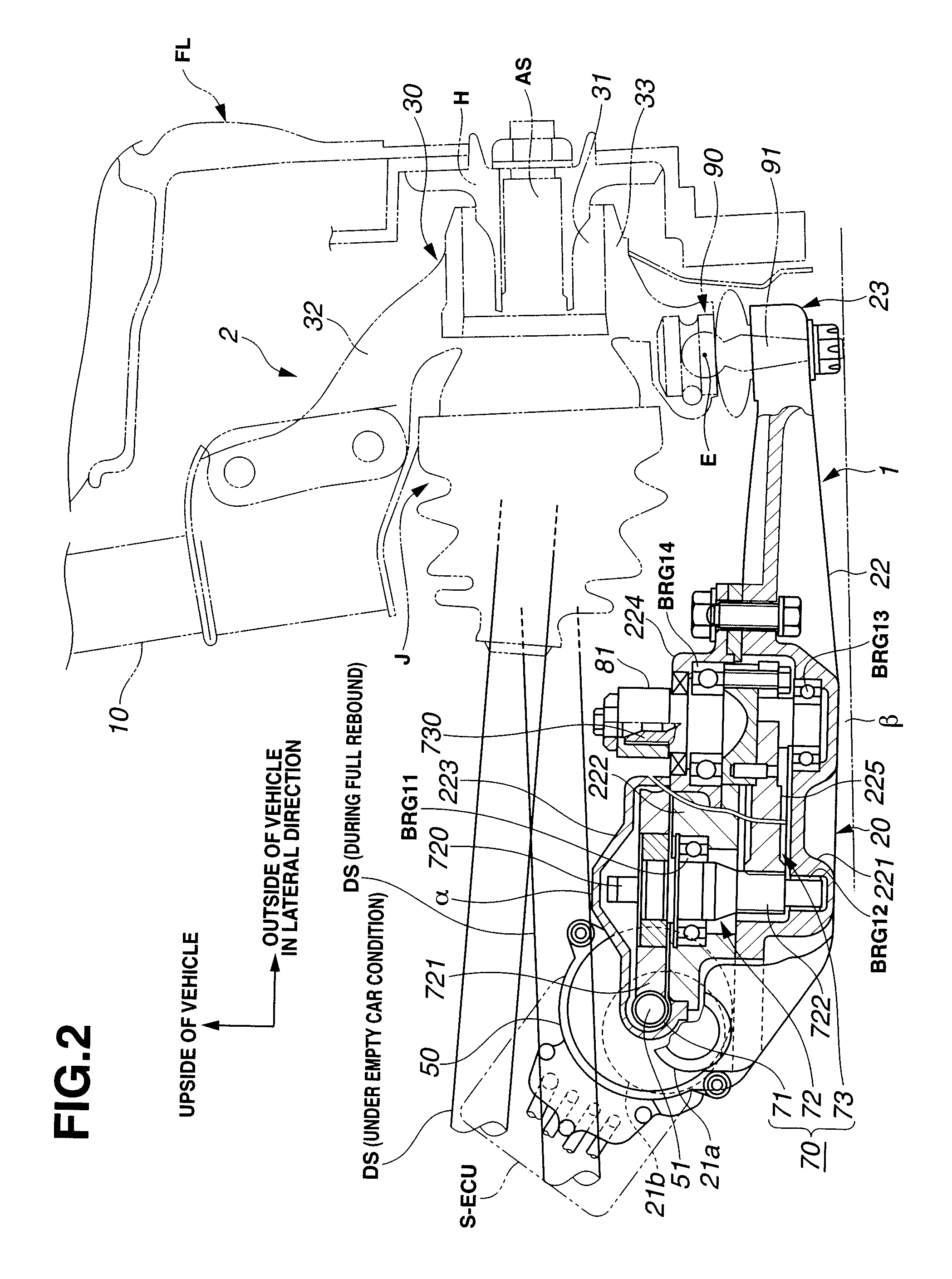
[0087]In addition to the steering system configurations (1), (2), (3), (6), and (7) and their operation and effects of the steering apparatus of the first embodiment, the steering apparatus of the second embodiment can further provide the following operation and effects by system configurations (9), (10), (11), (12), and (13).

[0088](9) Lower arm 20 is pivotally supported on the vehicle body by means of two supporting portions 21a, 21b spaced apart from each other, and additionally motor 50 is installed between these supporting portions 21a, 21b.

[0089]As set forth above, motor 50, which serves as a major heavy load of the steering actuator, is arranged in close proximity to the pivot of oscillating motion (pivoting motion) of lower arm 20 (that is, the straight line through two supporting portions 21a, 21b). Thus, the distance between the install...


PUM


Abstract

A steering apparatus includes an axle housing rotatably supporting a wheel hub on which a steered road wheel is installed, and a lower suspension-system control arm adapted to be oscillatingly supported at one end on a vehicle body and having a turning portion provided at the other end for pivotably supporting the axle housing by the turning portion. An electric motor is installed on the lower arm for turning the axle housing by a driving force produced by the motor. A rotation axis of the motor and a pivot of the axle housing are arranged to be offset from each other.

Description

TECHNICAL FIELD[0001]The present invention relates to a steering apparatus, and specifically to an automotive steer-by-wire (SBW) vehicle steering system configured to steer a plurality of steered road wheels independently of each other by means of respective steering actuators.BACKGROUND ART[0002]In recent years, there have been proposed and developed various automotive steer-by-wire (SBW) vehicle steering systems in which a steering reaction torque applied to a steering wheel and a steer angle at each steered road wheel can be arbitrarily determined. Such an automotive SBW vehicle steering apparatus generally employs a pair of steering actuators, each mechanically disconnected from a steering wheel. One such SBW vehicle steering apparatus, which is configured to steer a plurality of steered road wheels independently of each other by means of respective steering actuators, has been disclosed in Japanese Patent Provisional Publication No. 2007-55409 (hereinafter is referred to as “J...

Claims


Application Information

Patent Timeline
Patent Type & Authority Applications(United States)
IPC IPC(8): B62D5/04B62D7/00
CPCB60G7/006B60G2206/1116B60G2204/419B62D7/08B62D7/18B62D5/0418
Inventor SHIINO, KOHTAROTAKAHASHI, AKIRAYODA, TOSHIRO
Owner HITACHI ASTEMO LTD
Learn More