
Heat exchanger

a heat exchanger and heat exchanger technology, applied in the field of heat exchangers, can solve the problems of inability to recover thermal energy, loss of environmental protection, and user's trip over the raised heat exchanger cover of the tub, and achieve the effect of enhancing thermal energy transfer

Inactive Publication Date: 2009-03-05
PRODIGY ENERGY RECOVERY SYST
View PDF12 Cites 65 Cited by
  • Summary
  • Abstract
  • Description
  • Claims
  • Application Information

AI Technical Summary

Benefits of technology

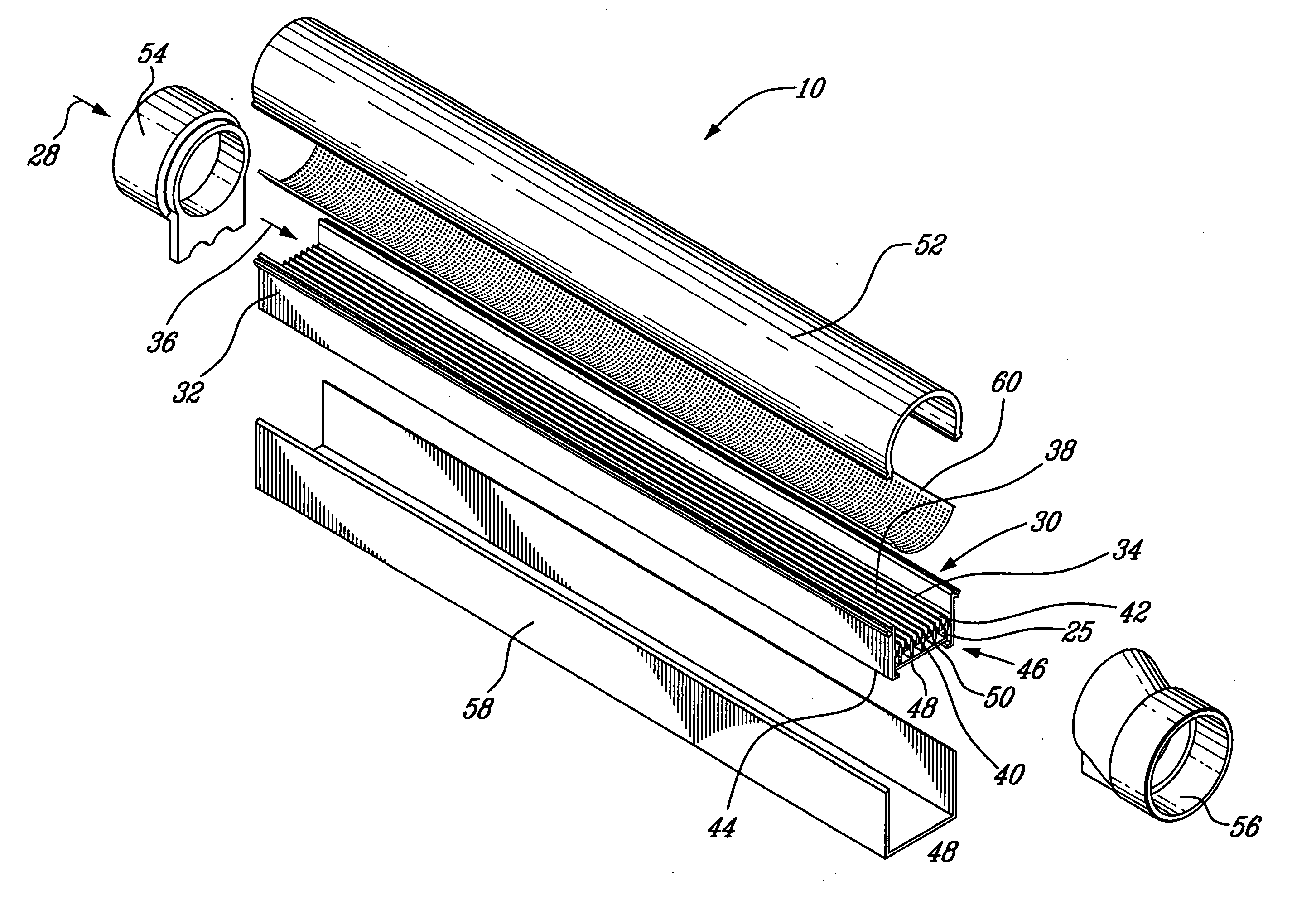
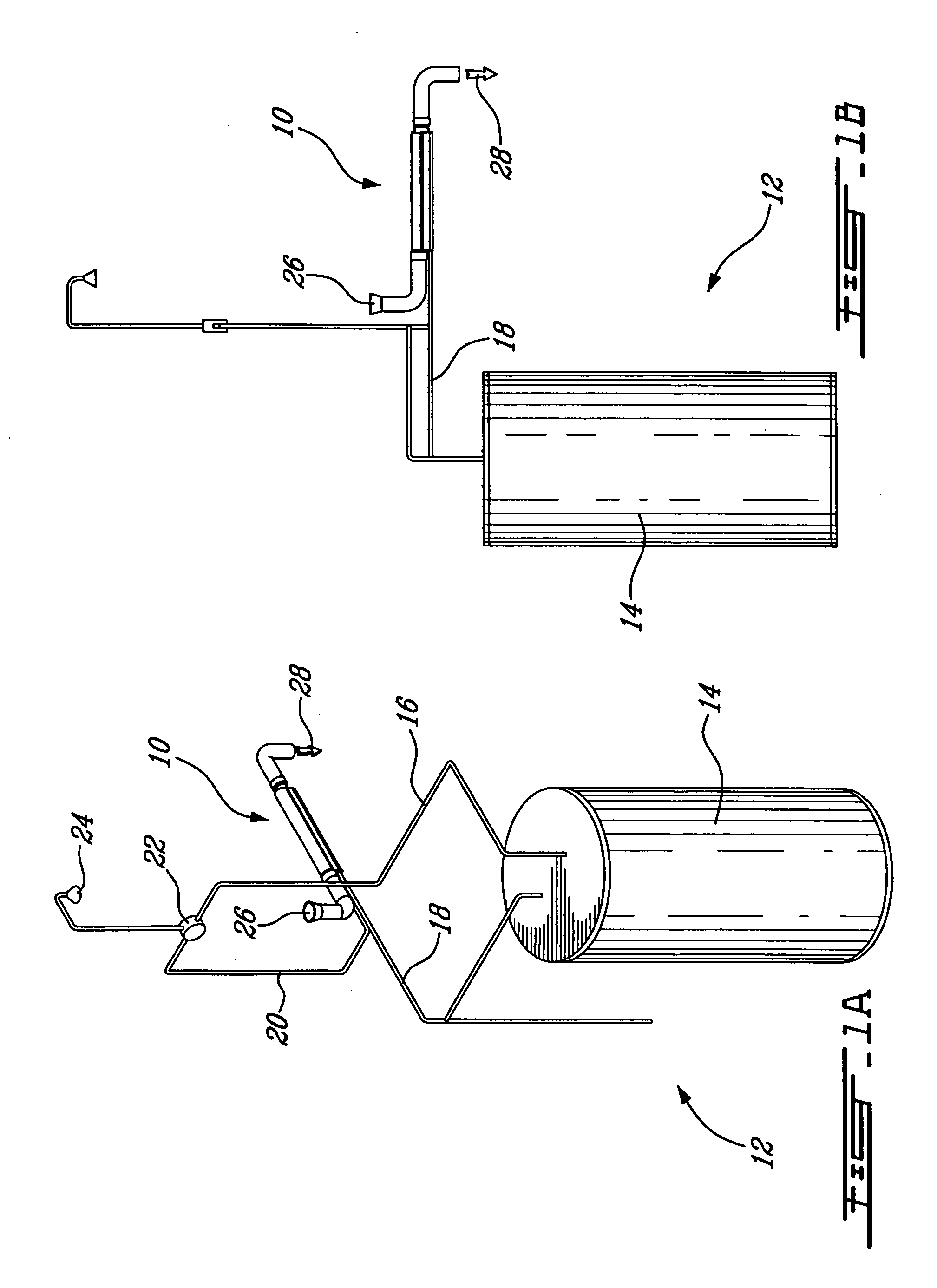
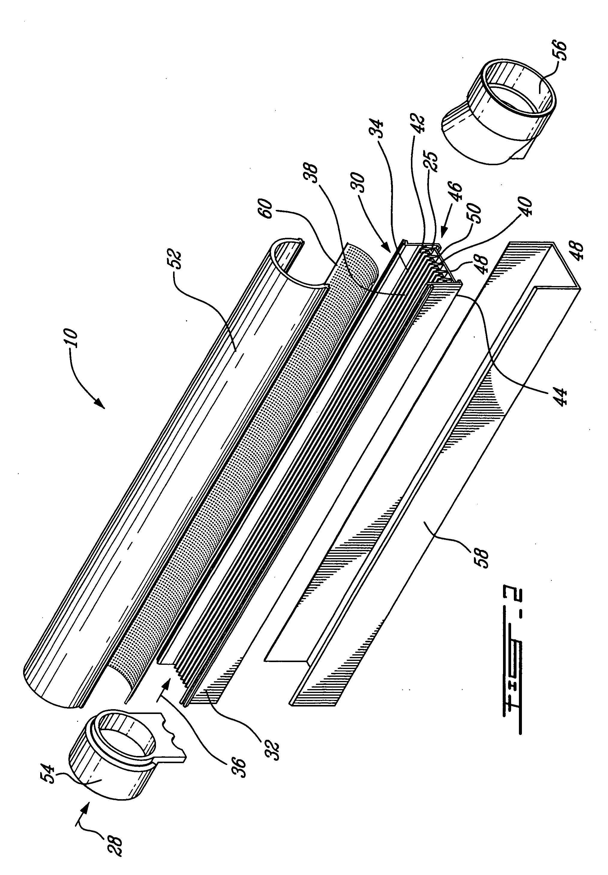
[0016]Accordingly, in one aspect there is provided a heat exchange apparatus, the apparatus comprising: a hollow blade member having a first fluid inlet and a first fluid outlet and a first fluid passageway for a first fluid extending therebetween, the blade member being sized and shaped for location in a second fluid passageway for a second fluid, the blade member being configured to enhance thermal energy transfer between the fluids as they flow along their respective passageways.
[0018]Accordingly in another aspect, there is provided a heat exchange apparatus, comprising: a central conduit having a conduit wall; an outer jacket substantially encasing the central conduit, the jacket being spaced apart from the conduit wall to define an enclosure and having a fluid inlet and a fluid outlet; a turbulator located in the enclosure, the turbulator having a first helical wire disposed in a clockwise orientation and a second helical wire disposed counterclockwise to the first helical wire so as to induce shear turbulent flow in a fluid as it flows through the enclosure and contacts the turbulator.

Problems solved by technology

The thermal energy, if not recovered, would be lost to the environment.
Disadvantageously, a user of the tub may trip over the raised heat exchanger cover.
The tub may also be difficult to clean and maintain.

Method used


Image

  • Heat exchanger
  • Heat exchanger
  • Heat exchanger

Examples


Embodiment Construction

Definitions

[0113]Unless otherwise specified, the following definitions apply:

[0114]The singular forms “a”, “an” and “the” include corresponding plural references unless the context clearly dictates otherwise.

[0115]As used herein, the term “comprising” is intended to mean that the list of elements following the word “comprising” are required or mandatory but that other elements are optional and may or may not be present.

[0116]As used herein, the term “consisting of” is intended to mean including and limited to whatever follows the phrase “consisting of”. Thus the phrase “consisting of” indicates that the listed elements are required or mandatory and that no other elements may be present.

[0117]As used herein, the term “turbulator” when referring to either a surface or to an insert having a surface that acts as a turbulator, is intended to mean that the surface has a plurality of projections extending away therefrom. Surface turbulators and inserted turbulators are used to increase con...


PUM


Abstract

Disclosed herein is a heat exchange apparatus, which comprises a hollow blade member having a first fluid inlet and a first fluid outlet and a first fluid passageway for a first fluid that extends between the inlet and the outlet. The blade member is sized and shaped to be located in a second fluid passageway for a second fluid. The blade member is configured to enhance thermal energy transfer between the fluids as they flow along their respective passageways.

Description

CROSS REFERENCE TO RELATED APPLICATIONS[0001]This application claims the benefit of the filing dates of U.S. provisional patent application Ser. No. 60 / 964,658, filed Aug. 14, 2007; U.S. provisional patent application Ser. No. 60 / 994,039, filed Sep. 17, 2007; U.S. provisional patent application Ser. No. 61 / 008,766, filed Dec. 21, 2007; and U.S. provisional patent application Ser. No. 61 / 134,666, filed Jul. 11, 2008, the disclosures of which are hereby incorporated herein by reference.FIELD OF THE INVENTION[0002]The present invention concerns heat exchangers, and more particularly to blade-type heat exchangers for recovering heat from fluids.BACKGROUND OF THE INVENTION[0003]Heat exchangers are well-known and widely used in a number of environments to recover thermal energy from fluids. The thermal energy, if not recovered, would be lost to the environment. Generally speaking, heat exchangers work by transferring heat from one fluid to another via a solid wall, which separates the two...

Claims


Application Information

Patent Timeline
Patent Type & Authority Applications(United States)
IPC IPC(8): F28F13/12F28D7/00
CPCF24D17/0005F24D2200/20F28D7/0008F28D7/10F28D7/16Y02B30/566F28F1/40F28F3/048F28F13/08F28F13/12F28F27/02F28D21/0012Y02B30/18Y02B30/56
Inventor HOFFMAN, MARCDEMEDEIROS, GILBERT
Owner PRODIGY ENERGY RECOVERY SYST
Learn More